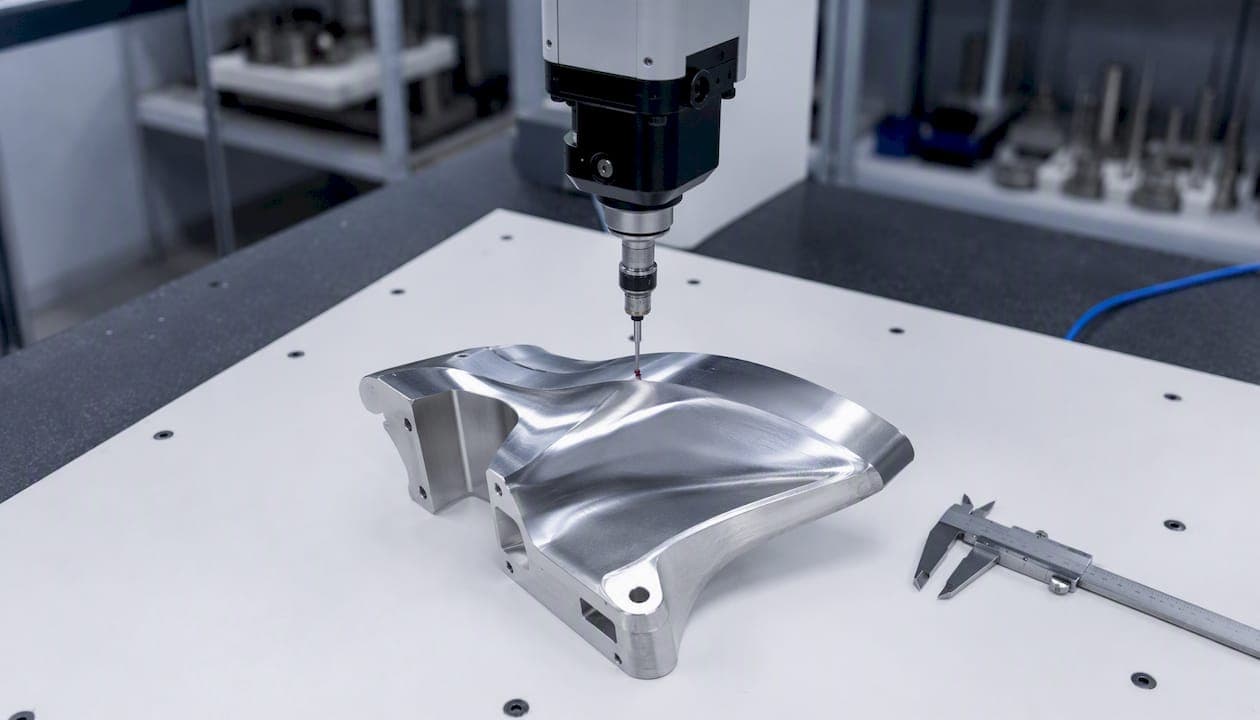
A surface profile tolerance — formally called profile of a surface in GD&T — bounds every point on a specified surface inside a three-dimensional tolerance zone defined relative to the true (nominal) profile. Three things matter immediately:
- What it controls: Form alone when no datums are referenced; form plus orientation when one datum is added; form, orientation, and location when a full datum reference frame is specified. This makes it one of the most versatile symbols in ASME Y14.5.
- How it's inspected: A coordinate measuring machine (CMM) or 3D scanner compares measured surface points against the CAD nominal. ISO 1101 and ASME Y14.5 both govern interpretation, though their bilateral/unilateral rules differ in subtle ways.
- The cost implication: Specifying profile instead of flatness or parallelism typically requires CMM or scanning equipment. That is a meaningful step up in inspection time and equipment cost, so the decision deserves deliberate justification.
Key Takeaways
Surface profile tolerance controls form, orientation, and location simultaneously — making datum discipline and CMM-capable inspection non-negotiable for any team specifying it on production drawings.
| Point | Details |
|---|---|
| What profile controls | Form only without datums; form, orientation, and location with a full datum reference frame. |
| Bilateral default | The tolerance zone splits equally on both sides of the nominal unless the U modifier specifies otherwise. |
| Primary inspection methods | CMM (touch or scanning probe) and structured-light/laser scanning compared against the CAD nominal. |
| Key drawing rules | Box all basic dimensions, reference datums when location matters, and avoid profile where flatness suffices. |
| QA-Report application | CMM data import, automated tolerance validation, and traceable PDF reports reduce profile inspection time from hours to minutes. |
Table of Contents
- What is surface profile tolerance and how is it written on a drawing?
- How does the 3D tolerance zone work in practice?
- Profile of a line vs. profile of a surface: which one do you need?
- When should you call out a surface profile on a drawing?
- How to show surface profile on drawings
- How do you measure and verify a surface profile?
- What does a practical profile inspection workflow look like?
- How does profile interact with other GD&T controls?
- Common mistakes in specifying and inspecting surface profile
- The case for discipline over complexity in profile tolerancing
- QA-Report makes profile inspection faster and audit-ready
- Sources
What is surface profile tolerance and how is it written on a drawing?
Profile of a surface is a three-dimensional tolerance zone equidistant from the theoretically exact (nominal) surface. Every point on the real surface must fall between two offset surfaces that follow the nominal contour. The zone width equals the tolerance value in the feature control frame (FCF).
Anatomy of the feature control frame
An FCF for profile of a surface contains, left to right:
- The symbol — a circle with a horizontal line through it (the profile-of-a-surface symbol per ASME Y14.5).
- The tolerance value — the total zone width in inches or millimeters.
- The U modifier (optional) — placed after the tolerance value when the zone is unilateral or unequally bilateral; written as U followed by the inside offset value.
- Datum references (optional) — A, B, C or whichever datums define the reference frame.
Three representative FCF configurations:
- Form only (no datums):
⌓ | 0.5 |— controls the shape of the surface but not its location or orientation in space. - Form + orientation (one datum):
⌓ | 0.5 | A— the zone is now oriented to datum A; parallelism and angularity are implicitly controlled. - Form + orientation + location (three datums):
⌓ | 0.5 | A | B | C— the full datum reference frame locks the zone in space; this is the most common configuration for mating surfaces and assembly interfaces.
Basic dimensions are required whenever profile controls location. Without boxed basic dimensions defining the true profile, the inspection program has no nominal to compare against. MMC and LMC modifiers do not apply to profile tolerances — the zone width is fixed regardless of the actual feature size.
How does the 3D tolerance zone work in practice?
The real surface must lie between two offset surfaces that follow the nominal contour, separated by the total tolerance value. Think of the nominal surface as a template, with one offset surface pushed outward (away from the material) and one pushed inward (into the material) by equal amounts when the disposition is bilateral.
Bilateral vs. unilateral disposition
By default, the tolerance splits equally on both sides of the nominal: a 0.4 mm bilateral zone places 0.2 mm outside and 0.2 mm inside the true profile. Engineers Edge confirms this bilateral default and notes that it applies regardless of feature size in most practical interpretations.
When the U modifier is used, the split changes. A callout of 0.6 U 0.4 means 0.4 mm inside the nominal and 0.2 mm outside — the total zone is still 0.6 mm, but it is shifted toward the material. The math: outside offset = total tolerance minus the U value; inside offset = U value.
Practical consequences for your team:
- A tight U value concentrates nearly all tolerance on one side, which can be useful for sealing surfaces or mating faces where one direction of deviation is functionally acceptable and the other is not.
- Unilateral zones require the CMM program to compare points against the correct side of the nominal — a setup error here produces false passes or false failures.
- Bilateral zones are easier to inspect and easier to manufacture to, so use unilateral only when the function genuinely demands it.
Pro Tip: When specifying a unilateral zone, add a note on the drawing explaining the functional reason. Inspectors and machinists who understand why a zone is offset make fewer setup errors than those who see an unfamiliar U modifier with no context.
Profile of a line vs. profile of a surface: which one do you need?
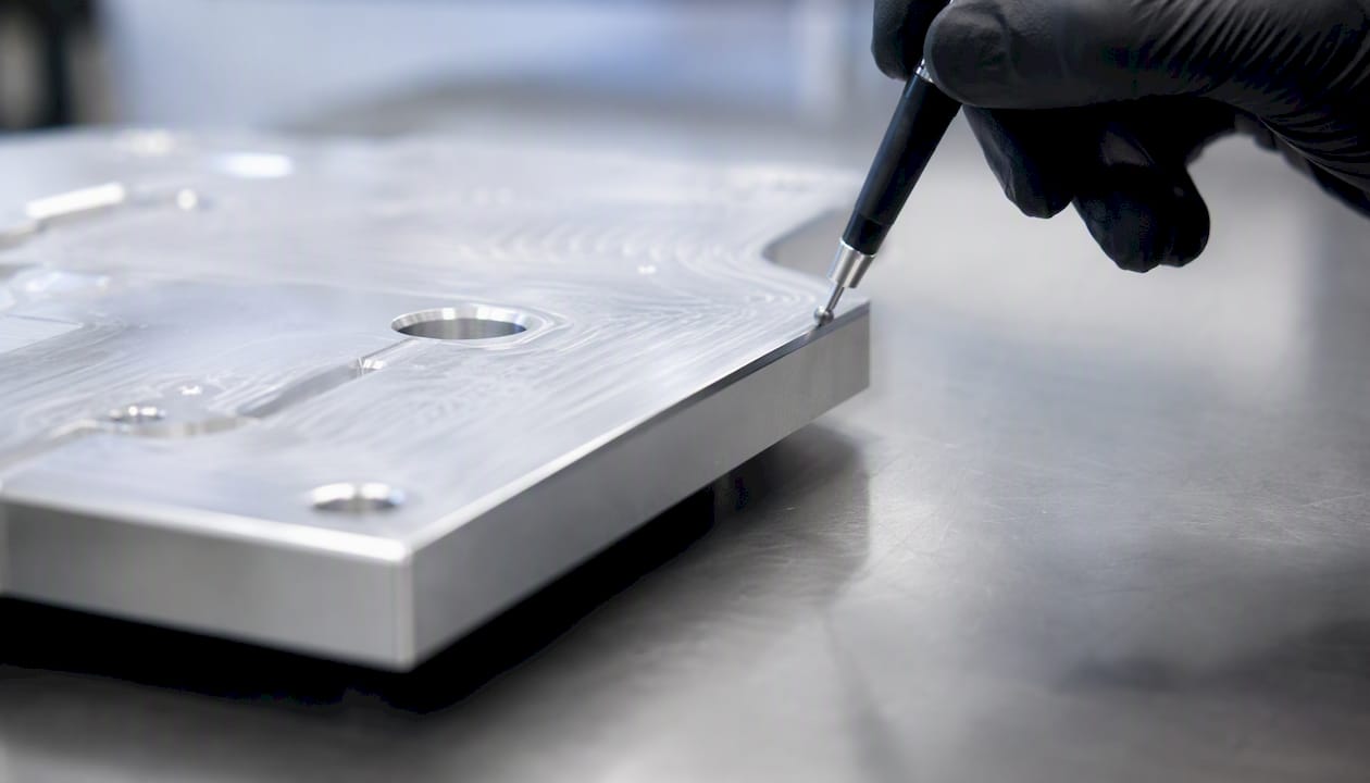
Profile of a line controls a single cross-sectional curve — a 2D slice through the surface at a specified location. Profile of a surface controls every point across the entire 3D surface. Redlux's practical GD&T primer makes the critical point clearly: a part can pass every individual line-profile check and still fail the surface-profile requirement, because the line checks miss deviations that occur between the measured cross-sections.
When line profile is sufficient
Line profile works well for extruded or prismatic shapes where the cross-sectional contour is the only concern — a constant-radius fillet along a straight edge, for example, or a 2D cam profile. It also suits situations where only one critical cross-section needs tight control while the rest of the surface carries a looser general tolerance.
When surface profile is required
Freeform aerodynamic surfaces, ergonomic contours, cast fillets that transition in three dimensions, and any surface defined by a CAD mesh rather than a 2D drawing view all demand the full-surface control. A turbine blade airfoil, an automotive body panel, or a medical implant contour cannot be adequately verified by line checks alone.
A part can carry both: a tighter line-profile callout on the most critical cross-section (say, the leading edge of an airfoil) alongside a looser surface-profile callout governing the rest of the blade. That combination gives you targeted control where it matters most without imposing the tightest tolerance everywhere.
When should you call out a surface profile on a drawing?
Use profile of a surface when simpler controls cannot capture the functional requirement. The decision checklist:
- Geometry complexity: Is the nominal surface defined by a 3D CAD model rather than 2D drawing views? If yes, profile is usually the right choice.
- Functional requirement: Does the surface affect aerodynamic performance, ergonomic fit, sealing, or optical function? Profile gives you the combined form-orientation-location control those applications need.
- Assembly interface sensitivity: Will this surface mate with a counterpart where gap or flush must be controlled across the full contact area? A single flatness callout won't catch a twisted or bowed surface that still meets local flatness.
- Measurement capability: Does your facility have CMM or scanning capability? Profile inspection requires it. Inspection cost rises when profile replaces flatness or parallelism — plan for a meaningful increase in inspection time and equipment needs.
When profile is the right call, it can replace multiple separate callouts (flatness + parallelism + position) with a single FCF, reducing allocation ambiguity and simplifying the drawing. When it is not the right call, it drives unnecessary cost. A planar surface that only needs to be flat to 0.05 mm does not need a profile callout — flatness is simpler to specify, simpler to inspect, and cheaper to verify. See the precision machining tolerances guide for process capability context that helps you set realistic tolerance values.
Pro Tip: Prefer flatness or cylindricity when only one aspect of form needs control. Reserve profile for surfaces where the nominal geometry is freeform, where combined form-orientation-location control is genuinely required, or where the CAD model is the authoritative nominal.
How to show surface profile on drawings
A profile callout is only as good as the information that supports it. Three elements must be present and correct:
Basic dimensions
Every dimension that defines the true profile's location and shape must be boxed (basic). Missing or unboxed basic dimensions leave the inspection program without a nominal, which means the CMM operator must make assumptions — and assumptions produce inconsistent results across facilities and audits.
For freeform surfaces, the drawing note "Profile per math data" or "True profile per CAD model, Rev X" is the accepted approach under ASME Y14.5. The CAD file becomes the normative nominal, and the FCF references it. Always identify the CAD revision explicitly.
Datum references
When the profile callout controls orientation or location, the datum reference frame must be fully defined. Datum A typically establishes the primary plane, B the secondary constraint, and C the tertiary. The FCF must list them in the correct precedence order. Omitting datums when location matters is one of the most common drawing errors — the result is an inspection that controls form but ignores whether the surface is in the right place.
Callout examples
- (A) Form-only FCF:
⌓ | 0.8 |— no datums; controls shape of the surface only. Use for freeform surfaces where location is controlled elsewhere. - (B) FCF with A, B, C datums:
⌓ | 0.5 | A | B | C— full datum reference frame; controls form, orientation, and location. Standard for mating surfaces and assembly interfaces. - (C) U modifier with unequal split:
⌓ | 0.6 U 0.4 | A | B— 0.4 mm inside the nominal, 0.2 mm outside. Use when one side of the nominal is functionally critical (sealing face, mating surface).
The "all over" modifier (two circles on the FCF leader line) extends the callout to every surface of the part. Use it deliberately — it commits every surface to CMM-level inspection.
How do you measure and verify a surface profile?
CMM and optical scanning are the standard production methods. Each has a distinct role depending on part geometry, required throughput, and tolerance tightness.
Measurement setup checklist
Before running a profile inspection program, verify:
- Datum establishment: Fixtures must constrain the part in the same orientation as the drawing's datum reference frame. A datum shift here propagates through every measured point.
- Probe/stylus selection: Stylus length and tip diameter affect access and measurement uncertainty. Qualify the stylus configuration before the production run.
- Point density: Sparse point clouds miss local deviations. For tight tolerances (under 0.2 mm), increase point density at high-curvature regions.
- Filtering and best-fit rules: Confirm whether the CMM program uses a constrained best-fit (datum-locked) or a free best-fit. Free best-fit can mask location errors.
- Calibration verification: Verify the CMM's calibration status and artifact traceability before each inspection session, not just at scheduled intervals.
For readers new to CMM setup fundamentals, the CMM inspection guide covers probe qualification, fixture design, and measurement uncertainty in practical terms.
ASME Y14.5 and ISO 1101 permit slightly different interpretations of bilateral disposition and datum precedence. If your supply chain spans both U.S. and European facilities, confirm which standard governs each drawing before comparing CMM results.
What does a practical profile inspection workflow look like?
A repeatable, auditable workflow removes the guesswork from profile acceptance. Here is the sequence your team should follow:
- Extract the true profile definition. Pull the CAD nominal (STEP or IGES) and confirm the drawing revision matches the CAD revision. Identify all basic dimensions and datum references on the drawing.
- Set up the CMM program. Build the measurement routine against the CAD nominal. Define datum targets and constrain the alignment to match the drawing's datum reference frame exactly.
- Verify datum transfer. Run a datum qualification check before measuring the part. If the fixture or datum surfaces are out of spec, every downstream measurement is suspect.
- Execute the scan or point measurement. Follow the point-density plan. For freeform surfaces, use a scanning probe or structured-light scanner to capture sufficient coverage. Document the operator ID, fixture ID, CMM program revision, and date.
- Import data and map to the nominal. Load the point cloud or CMM output into your inspection software. Map measured points to the CAD nominal using the constrained datum alignment — not a free best-fit. Tools like QA-Report's CMM import automate this mapping and flag misalignments before they become false results.
- Run tolerance validation. The software compares each measured point to the tolerance zone boundaries. Out-of-tolerance points are flagged with their deviation magnitude and location.
- Generate the inspection report. The report must include: max deviation value and location, a deviation map (color-coded surface plot), a histogram of deviations across the surface, pass/fail status per surface zone, and a traceable link to the drawing and CAD revision.
Composite profile strategies
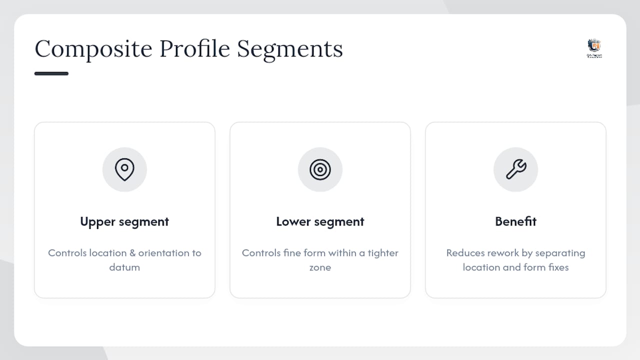
When a surface has both a tight form requirement and a looser location requirement, a composite (stacked) FCF separates the two. The upper segment controls location and orientation relative to the datum reference frame; the lower segment controls fine form within a tighter zone. This approach reduces rework by letting the machinist correct location errors independently of form errors — a significant advantage on complex multi-axis parts.
Pro Tip: Include the CMM program revision number in every inspection report. When a measurement dispute arises months later, the program revision is the fastest way to reconstruct exactly what was measured and how the datum alignment was applied.
How does profile interact with other GD&T controls?
Profile of a surface without datums is functionally analogous to flatness or cylindricity — it controls form only, with no orientation or location constraint. The key difference is that flatness applies to planar surfaces and cylindricity to cylindrical ones, while profile applies to any geometry including freeform. MetricMech's complete guide documents how adding datums progressively introduces orientation control (analogous to parallelism or perpendicularity) and then location control (analogous to position).
Replacing multiple callouts with one profile
A planar surface that carries separate flatness, parallelism, and position callouts can often be replaced with a single profile FCF referencing the full datum reference frame. The advantage: one tolerance zone, one inspection routine, no allocation conflicts between the three separate controls. The disadvantage: the inspection now requires a CMM capable of verifying all three aspects simultaneously, whereas a surface plate and dial indicator could previously verify flatness alone.
Stack-up interactions
Profile tolerances interact with size tolerances and assembly stacks in ways that simple form controls do not. Tolerance stack-up analysis must include profile contributions for both worst-case and RSS calculations. For a boss-and-hole assembly where the boss surface carries a profile callout, the profile tolerance adds directly to the positional stack. Specialized stack-up software handles profile contributions correctly; spreadsheet-based stacks often omit them, producing optimistic assembly predictions.
Common mistakes in specifying and inspecting surface profile
Avoiding these errors saves rework cycles and prevents false failures from reaching the customer.
Specification errors:
- Missing or unboxed basic dimensions. The most common drawing error. Without boxed basics, the inspection program has no normative nominal.
- Using profile where flatness suffices. A flat mounting pad does not need a profile callout. Flatness is cheaper to specify and cheaper to inspect.
- Omitting datum references when location matters. A form-only profile callout on a surface that must also be in the right place relative to a mating feature will pass inspection even when the surface is badly located.
- Specifying tolerances tighter than process capability. A 0.05 mm bilateral profile on a cast surface is almost always unreachable without secondary machining. Match the tolerance to the process. The precision machining tolerances reference provides process-capability benchmarks by manufacturing method.
Inspection errors:
- Poor datum transfer. If the fixture does not constrain the part in the drawing's datum reference frame, every measured deviation is relative to the wrong reference.
- Insufficient point density. A 20-point CMM check on a 300 mm freeform surface will miss local high spots. Increase density at high-curvature regions and near functional interfaces.
- Free best-fit alignment. Using a free best-fit when the drawing specifies a datum-locked alignment masks location errors and produces false passes.
- Skipping calibration verification. Running a profile inspection on an uncalibrated CMM produces results that cannot be defended in an audit.
Remediation steps:
- Re-examine the FCF and confirm datum references match the functional requirement before revising the drawing.
- Update the CMM program to use constrained datum alignment and increase point density at problem areas.
- Run a gauge R&R study on the measurement setup before committing to a production inspection plan.
The case for discipline over complexity in profile tolerancing
Profile of a surface is the most powerful symbol in the GD&T toolkit — and that power is exactly why it gets misused. The most common pattern: a designer specifies profile on every surface because it feels thorough, and the quality team inherits an inspection plan that requires full CMM coverage on parts that could have been verified with a surface plate and a few diameter checks.
The better discipline is to ask, for each surface, what functional failure mode you are actually preventing. Aerodynamic surfaces, sealing faces, and precision assembly interfaces genuinely need the combined form-orientation-location control that profile provides. Structural brackets, mounting pads, and non-functional fillets usually do not. Concentrating profile callouts on the surfaces where they matter keeps inspection cost proportional to risk.
Datum discipline is the other half of the equation. A profile callout without a well-designed datum reference frame is an inspection waiting to fail. The datum sequence must reflect the assembly sequence — the surface that contacts the mating part first should be datum A. When that logic is reversed or ignored, the CMM measures the part in a reference frame that does not match how it assembles, and the results are systematically misleading.
Automating CMM data import and tolerance validation, rather than manually transcribing point deviations into a spreadsheet, is where teams recover the most time. The overhead of profile inspection drops substantially when the data flows directly from the CMM into a structured report with automated pass/fail flags. That is where the economics of profile tolerancing start to make sense even for mid-volume production.
QA-Report makes profile inspection faster and audit-ready
Validating a surface profile tolerance manually — transcribing CMM deviations, building deviation maps in a spreadsheet, and assembling a PDF report by hand — takes hours per part. QA-Report eliminates that overhead.

The platform imports CMM output directly, maps measured points to the CAD nominal using your datum reference frame, and auto-flags every out-of-tolerance deviation with its magnitude and location. Deviation maps, histograms, and pass/fail summaries generate automatically. Every report carries a traceable link to the drawing revision and CMM program, satisfying AS9100, ISO 9001, and PPAP audit requirements without manual assembly.
For quality teams running first article inspections on profile-toleranced parts, that means a complete, audit-ready FAI report in minutes rather than hours. Start a free trial or explore the CMM inspection software feature page to see how the import and validation workflow applies to your parts.
Sources
The sources below are the normative and practical references for surface profile tolerance in U.S. manufacturing practice. This article follows ASME Y14.5 as the governing standard, with notes on ISO 1101 differences where they affect inspection interpretation.
- GD&T Profile of a Surface: Complete Guide | MetricMech
- Profile of a Surface | GD&T Basics
- Profile of Surface Tolerance | Engineers Edge
- Understanding Surface Profile Tolerance in Engineering and Manufacturing