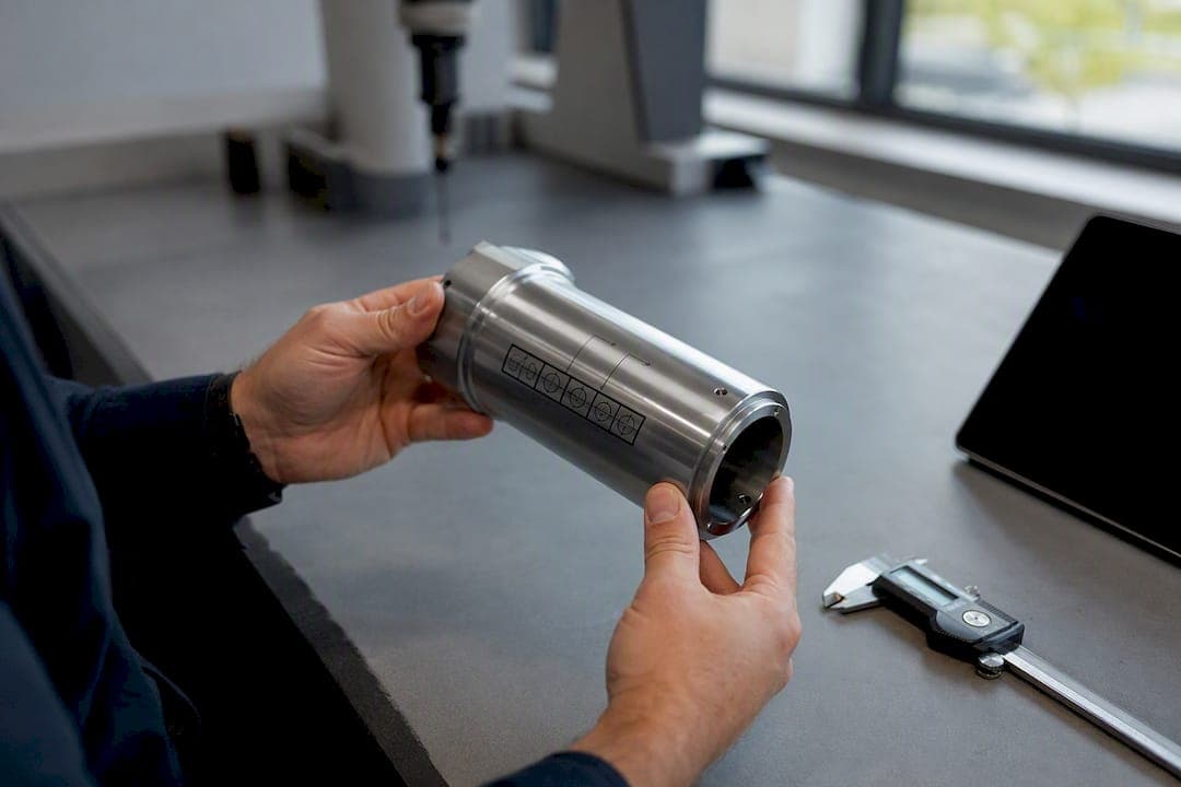
A feature control frame is the rectangular callout box in GD&T drawings that packages a geometric requirement into one readable string: a symbol, a tolerance zone, applicable modifiers, and the datum references that anchor the measurement. It is the single most information-dense annotation on a mechanical drawing, and misreading one is one of the fastest ways to build a part that fails inspection for reasons no one predicted.
Every feature control frame contains up to four pieces of information, read left to right:
- The geometric characteristic symbol (flatness, position, profile, runout, and others)
- The tolerance value, sometimes with a diameter symbol (⌀) in front of it
- Material condition modifiers like Ⓜ (MMC) or Ⓛ (LMC), when they apply
- Datum references, in order of precedence, when the control needs them
Design engineers use the frame to state exactly how much a feature is allowed to deviate. Quality inspectors use the same frame to decide what to measure, in what order, and against which reference surfaces. Get the reading wrong in either direction, and you either build a part that's tighter (and pricier) than it needs to be, or one that passes a bad inspection and fails in the field.
Key Takeaways
A feature control frame is decoded left to right, symbol first, and its datum references and modifiers determine both the true tolerance zone and the correct inspection sequence.
| Point | Details |
|---|---|
| Read order is fixed | Symbol, tolerance zone, modifiers, then datums, always in that left-to-right sequence. |
| Form controls skip datums | Flatness, straightness, circularity, and cylindricity apply to a single surface, so no datum reference is needed. |
| MMC changes the math | Bonus tolerance equals the feature's departure from MMC and must be recorded, not assumed. |
| Datum order drives fixturing | Primary, secondary, tertiary datums map to the 3-2-1 locating principle and set inspection sequence. |
| Automate the mapping | Linking ballooned FCFs directly to measurement data cuts transcription errors in dimensional reports. |
Table of Contents
- Parts of a Feature Control Frame: What Each Compartment Means
- How Do You Read Sample Feature Control Frames?
- What Are MMC, LMC, and RFS, and How Does Bonus Tolerance Work?
- From FCF to Inspection Report: CMM, Gaging, and Reporting Workflow
- Common Misreads and Best Practices for Feature Control Frames
- How QA-Report Turns Feature Control Frames Into Audit-Ready Reports
- What Engineers Get Wrong About Feature Control Frame Literacy
- Sources
Parts of a Feature Control Frame: What Each Compartment Means
Every feature control frame is built from compartments, and each one answers a specific question about the requirement. Learning to parse them in order is the fastest way to gain real GD&T fluency.
- The geometric characteristic symbol sits in the first compartment and tells you which of the fourteen ASME symbols applies. These fall into five families: form (flatness, straightness, circularity, cylindricity), orientation (parallelism, perpendicularity, angularity), location (position, concentricity, symmetry), profile (line and surface), and runout (circular and total). The symbol alone tells you whether datums will even be relevant.
- The tolerance zone value comes next, and its shape depends on the symbol. A plain number means a zone bounded by two parallel planes or lines. A ⌀ prefix means the zone is cylindrical, which is standard for position callouts on holes and pins because the feature's axis can wander in any direction, not just up-down or side-to-side.
- Material condition modifiers follow the tolerance, appearing as circled letters: Ⓜ for Maximum Material Condition, Ⓛ for Least Material Condition. If no modifier appears, the default under ASME Y14.5 is Regardless of Feature Size (RFS), meaning the stated tolerance applies no matter what size the feature actually measures.
- Datum reference compartments close out the frame, listed in order of precedence: primary, secondary, tertiary. This is also the sequence in which a fixture or CMM should touch the part.
Pro Tip: If a feature control frame stops after two compartments, don't assume something's missing. Form controls like flatness and straightness inherently apply to a single surface in isolation, so they typically carry no datum references at all.
How Do You Read Sample Feature Control Frames?
The best way to build fluency is to decode real examples the way you would encounter them on a drawing. Feature control frames are always read left to right, and the compartment count changes with the control type.
- Position: ⌖ | ⌀ 0.010 Ⓜ | A | B | C. This reads: the position tolerance zone is a cylinder 0.010 inches in diameter, applied at Maximum Material Condition, referenced to primary datum A, secondary datum B, and tertiary datum C. Because MMC is called out, the hole earns bonus tolerance as its actual size departs from the MMC limit. A hole drilled slightly oversized gets a looser position zone, not a tighter one.
- Flatness: 0.002, standalone, no datums. This reads: every point on the surface must fall within two parallel planes 0.002 inches apart. There's no reference frame because flatness only cares about the surface's relationship to itself. Measurement typically uses a CMM point cloud or a surface plate and dial indicator sweep.
- Profile: a profile-of-a-surface symbol with a tolerance value and datums A, B, C behaves differently. The datums control the profile's orientation and location in space, not just its shape, so the same numeric tolerance can mean a much stricter requirement than flatness alone.
- Runout: circular runout controls a single circular element as a part rotates around a datum axis; total runout controls the entire surface simultaneously. The difference matters because total runout catches combined form and orientation errors that circular runout can miss.
One detail trips up even experienced readers: a missing ⌀ symbol on a position callout means the zone is bounded by parallel planes, not a cylinder, which changes the actual measured volume of acceptable variation substantially.
What Are MMC, LMC, and RFS, and How Does Bonus Tolerance Work?
Material condition modifiers change how much tolerance a feature actually gets, and they're one of the most commonly misapplied elements in GD&T.
- MMC (Maximum Material Condition) is the condition where a feature contains the most material: smallest hole diameter, largest pin diameter.
- LMC (Least Material Condition) is the opposite: largest hole, smallest pin.
- RFS (Regardless of Feature Size) applies whenever no modifier is shown, meaning the stated tolerance is fixed no matter the feature's actual size.
Bonus tolerance shows up when Ⓜ or Ⓛ is called out. It's calculated as the difference between the feature's actual mating size and its MMC or LMC limit, and it's added directly to the stated position tolerance. A hole toleranced at ⌀ 0.010 Ⓜ that comes in 0.005 inches larger than its MMC limit effectively gets a 0.015-inch position zone. This relationship is central to how designers balance functional requirements against manufacturability, and skipping it in a report understates how much variation actually passed.
The practical payoff shows up on the shop floor: MMC callouts are what make functional go/no-go gaging possible for simple hole patterns, because the gage pin diameter is fixed at the worst-case condition. Complex profiles or features without a clean MMC relationship still need a CMM.
From FCF to Inspection Report: CMM, Gaging, and Reporting Workflow
Reading a feature control frame correctly is only half the job. Translating it into a measurement plan, and then into a defensible report, is where inspection teams either save hours or lose them.
- Establish the datum structure first. Set up your fixture or CMM alignment in A, B, C order before touching a single feature dimension, matching the frame's stated precedence exactly.
- Choose your measurement method based on the control type. Simple position tolerances at MMC on hole patterns are strong candidates for functional gaging, which can cut inspection cycle time significantly compared to point-by-point CMM measurement. Profile tolerances with multiple datum references, or any surface with a complex form, generally need a CMM to capture enough points for a reliable result.
- Record actual mating size whenever an MMC or LMC modifier is present. Without that number, you can't calculate bonus tolerance, and your report will show a feature as marginal or failing when it actually passed with room to spare.
- Present bonus tolerance explicitly in the report, not folded silently into a pass/fail flag, so anyone reviewing the data later understands why a feature that measured outside the base tolerance still passed.
The handoff between CAD annotation and shop-floor measurement is where a lot of this breaks down in practice. Drawing tools enforce rules like leader perpendicularity and frame attachment to reduce ambiguity at the annotation stage, but that discipline only pays off if the ballooned dimensions on the drawing map cleanly to the measured values in your inspection report. Manual re-keying between the two is where transcription errors creep in, especially on drawings with 100 or more ballooned dimensions.
Common Misreads and Best Practices for Feature Control Frames
A handful of mistakes account for most of the rework tied to feature control frame interpretation, and nearly all of them are preventable with a consistent read-through habit.
- Missing the ⌀ symbol. Treating a cylindrical position tolerance as if it were bounded by flat planes changes the actual acceptable zone shape and size.
- Ignoring datum precedence order. Measuring or fixturing in the wrong sequence builds an entirely different reference frame than the one specified.
- Treating form controls like location controls. Flatness and straightness don't reference datums for a reason. Trying to tie them to a datum structure that isn't there is a design or reading error.
- Over-tightening tolerances defensively. Specifying RFS everywhere out of caution, when MMC would allow bonus tolerance, adds cost without adding function.
The best-practice checklist comes down to four habits: read every frame left to right without skipping compartments, confirm the tolerance zone's actual shape before measuring, verify how each datum feature is meant to be simulated, and think through fixture and gaging impact before locking in a tolerance value. Clear communication between design and inspection teams remains the single biggest lever for cutting rework tied to GD&T misreads, and looser, function-driven tolerances are almost always cheaper to manufacture than blanket tight ones. Keeping your workspace free of airborne particulate also matters more than most shops assume: contamination on a datum surface or gage pin introduces measurement noise that can look identical to a real out-of-tolerance condition, which is why dust control in manufacturing environments belongs on the same checklist as datum verification.
How QA-Report Turns Feature Control Frames Into Audit-Ready Reports
Reading a feature control frame correctly is the starting point. Turning that reading into a defensible, audit-ready record for every part in a batch is the harder, more repetitive part of the job, and it's where QA-Report's automatic drawing ballooning removes the manual mapping step between drawing and report.
- Ballooned FCF callouts link directly to measurement items in the inspection plan, so the symbol, tolerance, and datum structure travel with the dimension instead of getting re-typed.
- CMM data import auto-flags out-of-tolerance results and calculates bonus tolerance at MMC automatically, rather than leaving that math to a spreadsheet.
- The platform outputs audit-ready PDF reports formatted for FAI, AS9102, and PPAP requirements, with statistical summaries built in.
Pro Tip: When a batch shows a recurring out-of-tolerance flag on the same feature, QA-Report's integrated MES layer lets you trace it back through route cards and batch history to find whether the root cause is tooling wear or a fixture datum problem.
What Engineers Get Wrong About Feature Control Frame Literacy
Most GD&T training treats feature control frame reading as a memorization exercise: learn the symbols, learn the compartment order, done. That's backward. The compartments are the easy part. What actually separates a team that reads frames well from one that doesn't is whether they treat the datum structure as a physical instruction, not an abstraction on paper.
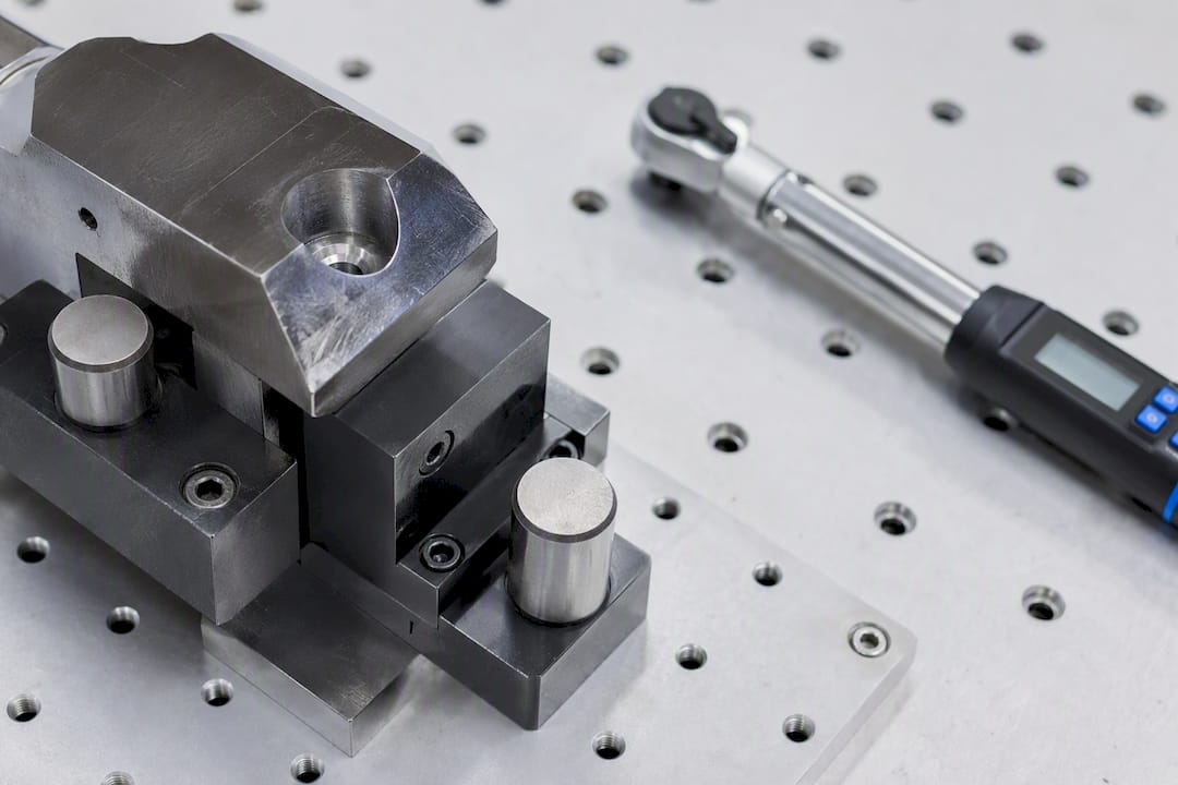
The conventional advice tells engineers to "specify datums carefully." Fine, but it rarely says what happens downstream when a fixture doesn't simulate that datum the way the drawing intended. That gap, between the theoretical DRF and the physical setup replicating it, causes more disputed rejects than any symbol misread ever will.
If there's one habit worth prioritizing over everything else in this article, it's this: before tightening a tolerance or arguing over an inspection result, trace the datum simulation back to the actual fixture. Ask whether the primary datum in the frame is genuinely the same surface the fixture contacts first. Most GD&T disputes I'd expect a quality team to encounter aren't symbol confusion. They're datum setups quietly drifting from drawing intent, and nobody catching it until a part fails for reasons the paperwork can't explain.
Sources
Datum letters in a feature control frame don't just label reference surfaces. They establish the Datum Reference Frame (DRF), the theoretical 3D coordinate system every measurement gets taken against, and they dictate the order a fixture or CMM operator has to follow.
That order maps directly to the classic 3-2-1 locating principle:
- ASME Y14.5 — Dimensioning & Tolerancing
- How to Read a Feature Control Frame in GD&T (2026)
- The Feature Control Frame | GD&T Fundamentals | Skill-Lync Resources
- Feature Control Frames — defining feature requirements
It's worth distinguishing a datum feature (the physical surface on the actual part) from a datum (the theoretical, perfect plane or axis that surface simulates). Fixture designers build tooling that simulates that theoretical condition as closely as possible, since inconsistent datum simulation between the drawing intent and the physical fixture is one of the most common sources of measurement disputes.
Advanced frames sometimes add degrees-of-constraint modifiers, bracketed letters like [u, v, w, x, y, z], that spell out exactly which translations and rotations a given datum feature controls. Misreading these leads to over-constraining a setup during inspection, which produces false rejects on parts that actually meet print.
Pro Tip: Datum order isn't a suggestion. If your fixture contacts datum B before datum A, you've built a different coordinate system than the one the designer intended, and every downstream measurement inherits that error.