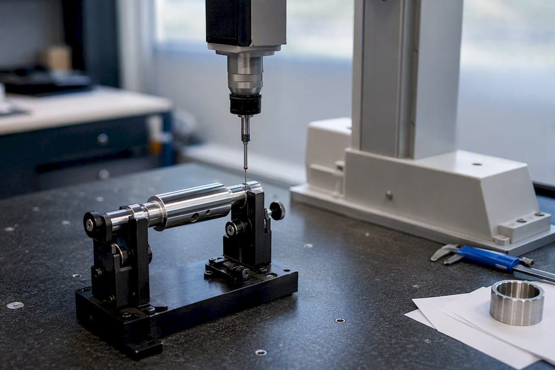
Circular runout limits wobble at one cross section; total runout limits wobble across an entire surface. Pick circular runout when you need to control a local journal or contact point, and pick total runout when the full length of a shaft or face has to behave consistently as it rotates. That's the core of the runout vs total runout question, and it drives everything else in this article.
Both controls get verified the same basic way: a dial indicator or CMM tracks how far a surface deviates during a full rotation, and the recorded spread between the highest and lowest reading is the Total Indicator Runout (TIR). Circular runout checks that spread at a single station. Total runout checks it as the indicator sweeps the whole feature at once.
Quick decision rule:
- Circular runout → bearing journals, individual grooves, localized contact zones
- Total runout → sealing surfaces, long shafts, tapered features, anything requiring continuous mating contact
- TIR → the number your indicator or CMM actually reports, regardless of which control you're checking
Table of Contents
- Runout vs Total Runout: Defining Circular, Total, and TIR
- How Do You Measure Runout on the Shop Floor and in the Lab?
- When Should You Specify Circular Runout vs Total Runout?
- Why Runout Beats Concentricity for Rotating Parts
- Runout Measurement Checklist and Common Mistakes
- How QA-Report Turns Runout Readings Into Audit-Ready Reports
- What Actually Matters When You Specify Runout
- Sources
Runout vs Total Runout: Defining Circular, Total, and TIR
Circular runout is a two-dimensional control. It applies independently to each circular element of a feature, meaning the inspector checks one slice of the cylinder or one radius of a face, then moves to the next slice and checks it separately. It catches out-of-roundness and axis offset at that one location, but it has no memory of what happened at the last station.
Total runout works in three dimensions. It evaluates the entire controlled surface simultaneously as the indicator traverses it during rotation, which means it folds in circularity, concentricity, and longitudinal form (taper, barrel, bow) all at once. A part can pass circular runout at every individual station and still fail total runout, because total runout is sensitive to how those stations relate to each other along the axis.
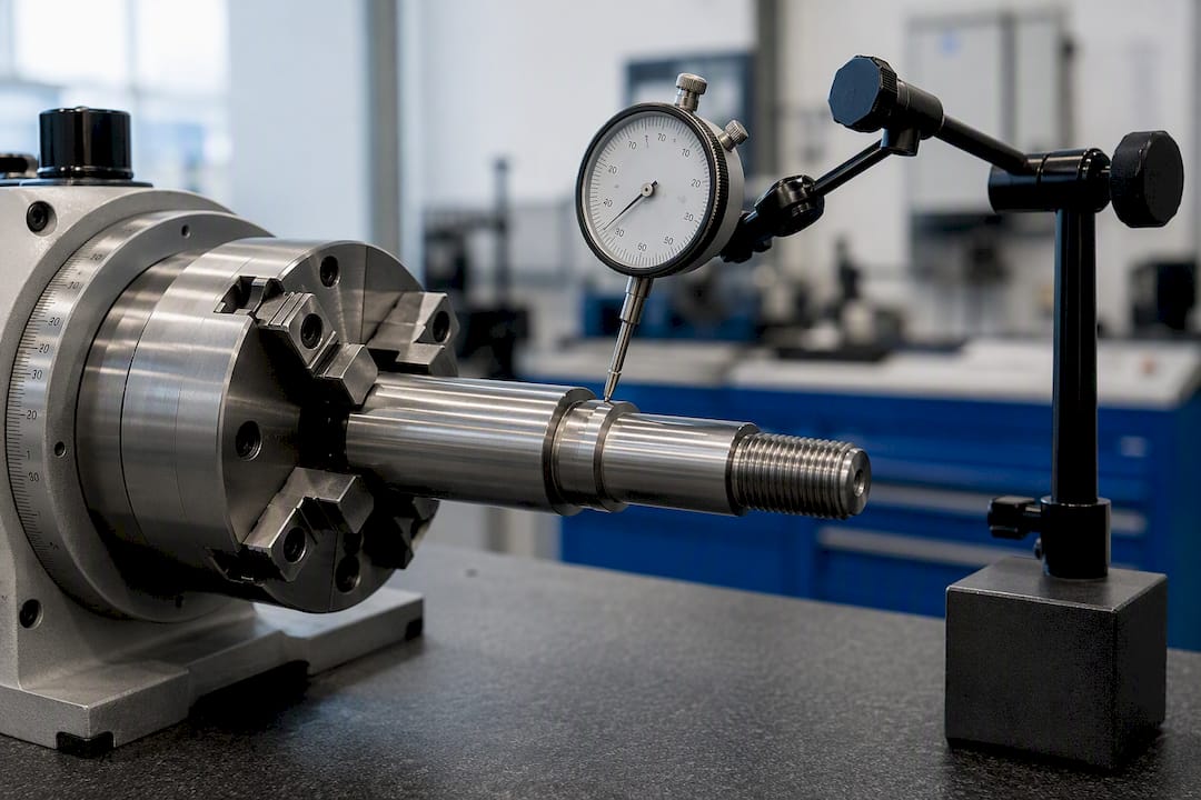
The value both methods actually produce is Total Indicator Runout, the difference between the maximum and minimum indicator reading during a check. When a machinist says "runout is 0.002 inches," they usually mean TIR, not the geometric callout itself.
Statistic to remember: Total runout is mathematically the more restrictive of the two controls, because a part that satisfies total runout automatically satisfies circular runout at every cross section, but the reverse isn't guaranteed.
- Circular runout: fast, local, blind to longitudinal trends
- Total runout: comprehensive, catches taper and bow, costs more inspection time
How Do You Measure Runout on the Shop Floor and in the Lab?
Dial indicator setups remain the workhorse for both controls, and the mechanics differ mainly in probe motion.
- Mount the part on its datum. Use V-blocks, centers, or a chuck that simulates the datum axis called out on the drawing.
- For circular runout, hold the indicator stationary at one axial position, rotate the part a full 360 degrees, and record the TIR at that station.
- For total runout, rotate the part continuously while simultaneously traversing the indicator along the full length of the surface, recording the worst TIR observed anywhere in that sweep.
- Repeat at multiple stations for circular runout if the drawing specifies more than one checked cross section.
- Cross-check with a CMM when tolerances are tight or the geometry is complex. A CMM samples far more points than a hand indicator can, and it computes runout mathematically from that dense point cloud rather than relying on a physical sweep.
Shop-floor dial indicator checks on a single feature often take just a couple of minutes once the part is fixtured; a CMM routine covering the same feature with dense sampling and a full report can take considerably longer to program and run, though it repeats without setup drift once dialed in.
Pro Tip: Datum simulation error is the single biggest hidden source of bad TIR readings. If your V-block doesn't match the actual datum diameter or your chuck has runout of its own, you're measuring your fixture, not your part. Verify your fixture's own runout before you trust a single number off the part.
When Should You Specify Circular Runout vs Total Runout?
Match the control to the failure mode you're actually trying to prevent, not to habit.
- Bearing journals and rotating contact points: circular runout usually suffices, since the concern is local wobble at the contact zone, not the whole shaft's behavior.
- Seals and sealing lands: total runout is often warranted because leakage depends on continuous contact along the entire sealing surface, not just one cross section.
- Long shafts: total runout catches taper and bow that circular runout, checked only at a few stations, can miss entirely.
- Tapered or contoured surfaces: total runout is close to mandatory, since the geometry itself depends on consistent longitudinal form.
Total runout is generally more restrictive and more expensive to inspect, so specifying it everywhere "to be safe" inflates cost without necessarily protecting function any better. A part that only needs to spin true at a bearing land doesn't need whole-surface control, and reviewing precision machining tolerance trade-offs early in design keeps that inspection burden proportional to the actual risk.
Why Runout Beats Concentricity for Rotating Parts
Concentricity was a common callout for decades, but it requires locating the median points of diametrically opposed surface elements, a calculation that demands dense CMM data and heavy postprocessing. That measurement burden is a big part of why concentricity was dropped as a recommended common control in ASME Y14.5-2018.
Runout sidesteps that problem because it measures actual surface behavior, the real wobble a bearing or seal will feel, using nothing more exotic than a dial indicator. That's also why industry practitioners generally prefer runout for rotating parts over concentricity.
Position tolerance remains the better call when you're controlling location relative to other features rather than rotational behavior. As a rule:
- Use runout when the part spins and surface wobble matters functionally
- Use position when static location relative to a datum system matters more than rotation
- Avoid concentricity unless a legacy drawing or contractual requirement specifically demands it
Runout Measurement Checklist and Common Mistakes
A repeatable setup prevents the disputes that erode trust between engineering and the inspection floor.
- Confirm the datum reference frame on the drawing before touching the part. Guessing at datums is the single most common source of rejected reports.
- Verify fixture runout independently of the part, especially on V-blocks and collets that see daily wear.
- Take multiple rotations rather than trusting a single sweep. Debris or a burr can spike one reading.
- Record TIR with units and the datum reference explicitly noted, not just a bare number.
- For total runout, confirm the traverse covered the full toleranced length, not just a convenient middle section.
- Apply the acceptance rule consistently, comparing worst-case TIR (not an average) against the drawing tolerance.
Three mistakes show up constantly on the shop floor. Inspectors sometimes measure from the wrong datum because the drawing's datum feature symbol wasn't clearly ballooned. Others undersample circular runout, checking only one station on a feature that clearly tapers, which quietly misses a total runout style failure. And a persistent one: treating a runout number as if it were a concentricity value, when the two controls answer genuinely different geometric questions.
Pro Tip: When a report shows a runout failure, check the fixture before you condemn the part. A worn or misaligned datum simulator, covered in more detail in this breakdown of datum-fixture mismatches, produces the same symptom as a genuinely bent shaft.
How QA-Report Turns Runout Readings Into Audit-Ready Reports
Manual transcription is where good runout data goes to die, whether it's a dial reading copied onto paper or a CMM export reformatted by hand. QA-Report imports CMM output directly, maps each measured point to the corresponding ballooned dimension on the drawing, and flags anything outside its runout tolerance automatically.
That mapping matters for AS9100 and ISO 9001 audits, where a reviewer needs to trace a specific TIR value back to its exact drawing callout, datum reference, and inspection date without reconstructing the logic from memory. Once a runout check clears validation, the platform generates a formatted PDF and logs the result against the part's batch record, keeping traceability intact from raw indicator sweep to final acceptance.
- Automatic mapping of CMM points to ballooned runout callouts
- Instant flagging when TIR exceeds the drawing tolerance
- PDF reports formatted for AS9100 and ISO 9001 audit trails
- Batch-level traceability tying every runout result to its part history
| Point | Details |
|---|---|
| Definitions differ by dimension | Circular runout checks one cross section; total runout checks the entire surface at once. |
| TIR is the shared unit | Both controls are measured the same way: max minus min indicator reading during rotation. |
| Match control to function | Use circular runout for local journals, total runout for seals and long shafts with taper risk. |
| Concentricity is largely obsolete | Runout replaced it for rotating parts because it's easier to inspect and reflects real surface behavior. |
| Fixture error skews results | Verify datum simulators before condemning a part on a failed runout reading. |
The single most important fact in specifying rotational GD&T is that circular runout controls one cross section while total runout controls the entire surface, and choosing between them should follow function, not habit.
What Actually Matters When You Specify Runout
The conventional advice on runout vs total runout usually stops at definitions, as if knowing the geometry were the hard part. It isn't. The hard part is fixture discipline, and most of the runout disputes I've seen traced back to a worn V-block or a misjudged datum simulator, not a genuinely out-of-tolerance part.
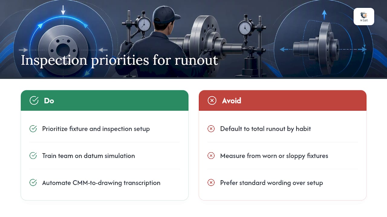
Engineers also overuse total runout more than they admit. It reads as the "safer" callout, but every unnecessary total runout spec adds real inspection time on a CMM or a slower manual traverse, for a functional risk that circular runout would have caught just as well. Ask what actually fails, not what looks more thorough on a drawing.
If you take one thing from this piece, prioritize your inspection setup over your GD&T literacy. A team that understands datum simulation cold, but is fuzzy on the exact ASME wording, will produce more reliable acceptance decisions than a team that can recite the standard but measures off a sloppy fixture. Software that ties CMM data to drawing callouts automatically, like QA-Report, removes the transcription risk, but it can't fix a bad fixture. That part is still on you.
— Michael Chen
Sources
- Total runout | GD&T Basics
- Circular runout vs total runout | Metal Cutting Knowledge Center
- Runout Vs. Total Runout | MeasureDay