
Position tolerance, also called true position, defines the maximum permissible deviation of a feature's actual center, axis, or center plane from its theoretically exact location as defined by basic dimensions and datums. The pass/fail test comes down to one formula: TP = 2 × √(Δx² + Δy²). If that calculated value is less than or equal to the tolerance stated in the feature control frame (plus any bonus tolerance earned at maximum material condition), the feature passes.
Here's the fast version, before we get into the mechanics:
- Measure the actual X and Y coordinates of the feature's axis or center, then subtract the nominal (basic dimension) values to get Δx and Δy.
- Calculate the radial deviation, r = √(Δx² + Δy²), then double it to get the diametral true position value.
- If the drawing calls out a material-condition modifier (MMC or LMC), add any earned bonus tolerance to the stated tolerance before comparing.
- Compare your computed TP against the total allowed tolerance. Under or equal passes; over fails.
Pro Tip: Keep your units consistent through the entire calculation. A mixed inch/millimeter entry is the single most common reason engineers get a "failed" part that actually passed.
Key Takeaways
Position tolerance passes or fails on one comparison: the calculated TP value against the drawing's stated tolerance plus any MMC-earned bonus tolerance.
| Point | Details |
|---|---|
| The core formula | TP = 2 × √(Δx² + Δy²), where Δx and Δy are measured minus nominal coordinates. |
| Cylindrical zones beat coordinate zones | A circular position zone gives roughly 57% more usable tolerance area than an equivalent square coordinate zone. |
| No modifier means RFS | A missing material-condition symbol defaults to Regardless of Feature Size, with zero bonus tolerance allowed. |
| Bonus tolerance requires actual size | MMC bonus equals the feature's measured size minus its MMC size, added to the stated tolerance before comparison. |
| Automate the calculation for volume work | QA-Report's measurement wizard applies the TP and bonus tolerance math automatically from CMM import and ballooned drawings. |
Table of Contents
- What Does Position Tolerance Control?
- How Do You Read a Position Feature Control Frame?
- How Do You Calculate True Position?
- What's the Difference Between RFS and MMC for Position?
- What Shape Is the Position Tolerance Zone?
- Why Do Datum Selection and Feature Shift Matter?
- What's the Right Workflow for Inspecting Position on a CMM?
- What Belongs in a True-Position Inspection Report?
- What Do Experienced Inspectors Watch For?
- Where Inspection Software Fits Into Position Tolerance Checks
- Where to Verify These Rules and Calculations
- Frequently Asked Questions
- Why Position Tolerance Gets Misapplied More Than It Gets Misunderstood
- Sources
What Does Position Tolerance Control?
Position tolerance is a geometric dimensioning and tolerancing (GD&T) control, denoted by the symbol ⌖, that governs the location of a feature of size, meaning a hole, pin, slot, or boss with its own diameter or width. Under ASME Y14.5, position doesn't control a single dimension the way a plus/minus tolerance does. It defines a three-dimensional zone, typically cylindrical for a hole or pin and a parallel-plane slab for a slot, inside which the feature's actual axis or center plane must fall relative to a datum reference frame.
That distinction between position tolerance and coordinate tolerancing matters more than most drawings suggest. A conventional plus/minus callout on X and Y creates a square tolerance zone. Position tolerance replaces that square with a circle of the same nominal size, and that circle gives you roughly 57% more usable tolerance area than the square zone it replaces. The corners of the square zone let a feature drift further off-axis diagonally than it does horizontally or vertically, an inconsistency that has nothing to do with function and everything to do with the geometry of rectangular coordinates. A cylindrical zone treats every direction of deviation equally, which is exactly how a mating pin or bolt sees the hole it needs to pass through.
Position tolerance also does something a coordinate tolerance can't: it captures orientation, not just location. When a hole is referenced to datums in a proper hierarchy, tilt and perpendicularity get folded into the same control. That's part of why practitioners often call position the most powerful control in the GD&T toolbox: it can enforce both where a feature sits and how it's oriented, in a single callout.
You'll see position tolerance applied constantly in:
- Bolt patterns, where multiple holes need to align with a mating flange or bracket.
- Hole locations on plates, brackets, and housings that accept dowels, screws, or shafts.
- Pin and boss placements on castings and molded parts that must nest into a mating assembly.
- Slot centerlines, where a center plane rather than an axis needs controlling.
Reach for position tolerance whenever a feature's job is to line up with something else during assembly. Reach for a simpler coordinate tolerance only when the feature is cosmetic, non-mating, or otherwise indifferent to precise alignment.
How Do You Read a Position Feature Control Frame?
A position callout packs a lot of information into a small box, and misreading any one compartment changes the entire tolerance. A typical feature control frame reads left to right as:
- The position symbol (⌖), identifying the type of control.
- A diameter symbol (Ø), present when the zone is cylindrical rather than a width-based slab.
- The tolerance value, the numeric size of the zone.
- A material-condition modifier, either Ⓜ for MMC or Ⓛ for LMC, if one applies.
- The datum reference frame, listed in priority order, usually primary, secondary, tertiary.
Take a callout that reads "⌖ Ø0.008 A|B|C Ⓜ". That says the hole's axis must fall within a cylindrical zone 0.008 inches in diameter, centered on its true position relative to datums A, B, and C in that order, and the tolerance can grow if the hole departs from its maximum material condition (its smallest permitted diameter).
Here's the trap that catches a surprising number of experienced engineers: if no modifier appears in the box, the control defaults to Regardless of Feature Size (RFS). There's no bonus tolerance, full stop. A missing symbol isn't an oversight to interpret charitably. It's a deliberate, enforceable condition under ASME Y14.5, and inspectors need to treat it that way even when the omission looks like it might have been unintentional on the drawing.
How Do You Calculate True Position?
Calculating true position is arithmetic, not judgment, which is exactly why it's such a reliable inspection tool. Once you have measured coordinates and nominal coordinates for a feature's axis, the process is fixed.
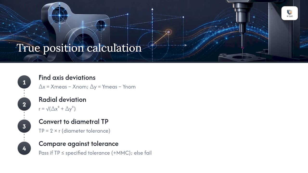
Step 1: Find the deviation in each axis.
Δx = X(measured) − X(nominal) Δy = Y(measured) − Y(nominal)
Step 2: Calculate the radial deviation.
r = √(Δx² + Δy²)
Step 3: Convert to diametral true position.
TP = 2 × r
That factor of two trips people up constantly, so it's worth explaining rather than memorizing. The tolerance zone is a cylinder specified by its diameter, not its radius. Your measured deviation, r, is a radial distance from the true center, essentially a radius of its own. To compare a radial measurement against a diameter-based tolerance, you have to double it. Skip that step and every part looks like it has half the deviation it actually does, which means you'll pass parts that should fail.
Step 4: Compare against the drawing tolerance.
If TP ≤ the specified tolerance (plus any bonus tolerance earned through MMC, covered next), the feature passes. If TP exceeds it, the feature fails.
Worked Example 1: Simple RFS Check
A drawing specifies a hole location with basic dimensions X = 2.000 in, Y = 1.500 in, and a position tolerance of Ø0.010 in at RFS (no modifier shown). Your CMM measures the actual hole center at X = 2.004 in, Y = 1.497 in.
- Δx = 2.004 − 2.000 = 0.004 in
- Δy = 1.497 − 1.500 = −0.003 in
- r = √(0.004² + (−0.003)²) = √(0.000016 + 0.000009) = √0.000025 = 0.005 in
- TP = 2 × 0.005 = 0.010 in
The calculated true position lands exactly at 0.010 inches, precisely on the tolerance limit. That's a pass, though it's the kind of borderline result that deserves a second look at your gage repeatability before you sign off on it.
Worked Example 2: A Failing Part
Same nominal position, same Ø0.010 tolerance, but the CMM now reads X = 2.006 in, Y = 1.492 in.
- Δx = 2.006 − 2.000 = 0.006 in
- Δy = 1.492 − 1.500 = −0.008 in
- r = √(0.006² + 0.008²) = √(0.000036 + 0.000064) = √0.0001 = 0.010 in
- TP = 2 × 0.010 = 0.020 in
A calculated true position of 0.020 inches against a 0.010-inch tolerance is a clean fail, at exactly twice the allowed deviation. There's no ambiguity here, and this is where having the raw Δx/Δy numbers in your report earns its keep: engineering can see immediately that the Y deviation is the larger contributor and adjust the process accordingly.
Adding Bonus Tolerance to the Comparison
When the feature control frame carries an MMC modifier, you don't compare TP against the stated tolerance alone. You first calculate how much bonus tolerance the feature has earned by departing from its maximum material condition, add that to the drawing tolerance, and compare TP against the new total. The next section walks through exactly how that bonus is computed, because it's the step most often done wrong on the shop floor.
What's the Difference Between RFS and MMC for Position?
RFS and MMC change how much tolerance a part actually gets, and confusing the two is one of the fastest ways to scrap a good part or pass a bad one.
RFS (Regardless of Feature Size) applies whenever no material-condition modifier is shown, and it's the default under ASME Y14.5. The position tolerance stays fixed no matter what size the feature actually measures within its own size tolerance. There's no bonus, no sliding scale. What's on the drawing is what you get.
MMC (Maximum Material Condition) is the condition where a feature contains the most material: the smallest allowable diameter for a hole, the largest allowable diameter for a pin or shaft. When a position callout includes the Ⓜ modifier, the feature earns bonus tolerance any time it departs from MMC, because a hole that's larger than its minimum size (or a pin that's smaller than its maximum size) leaves more clearance for assembly, so the position tolerance can loosen without threatening fit.
LMC (Least Material Condition) works the same way in reverse, tied to the least amount of material a feature can have. It shows up far less often, usually in wall-thickness or minimum-clearance applications rather than routine hole patterns.
The bonus tolerance formula is straightforward:
- Determine the feature's actual measured size (its diameter, for a hole or pin).
- Find the difference between that actual size and the MMC size stated on the drawing.
- That difference is the bonus tolerance, added directly to the stated position tolerance.
- Total allowed tolerance = stated tolerance + bonus tolerance.
Worked Bonus Tolerance Example
A hole is specified as Ø0.500 ± 0.002 in, with position ⌖ Ø0.010 Ⓜ. MMC for this hole is its smallest allowed size: 0.498 in.
Your CMM measures the actual hole diameter at 0.501 in.
Bonus tolerance = 0.501 − 0.498 = 0.003 in
Total allowed position tolerance = 0.010 + 0.003 = 0.013 in
If your calculated TP from the Δx/Δy method came out to 0.012 in, that part passes against the 0.013-inch total, even though it would have failed against the bare 0.010-inch drawing tolerance. This is precisely why MMC exists: it lets the tolerance breathe in proportion to the clearance the part actually has, instead of forcing every hole to the same rigid number regardless of how much room the mating fastener really needs.
Watch for these pitfalls, because they show up constantly in real inspection reports:
- Misreading a missing modifier as MMC because "that's usually what's intended." It isn't, unless the box says so.
- Applying one feature's bonus tolerance to a different feature in a pattern, especially in multi-hole assemblies where each hole has its own actual size and its own bonus.
- Mixing units mid-calculation, particularly on drawings that combine inch-based basic dimensions with a metric CMM output.
- Forgetting that bonus tolerance requires re-measuring actual feature size, not just re-measuring location. You need both numbers, every time.
Pro Tip: If a supplier keeps returning parts that fail position by a hair, check whether their inspection process is applying bonus tolerance at all. A lot of "borderline" position failures aren't borderline once the bonus is calculated correctly.
What Shape Is the Position Tolerance Zone?
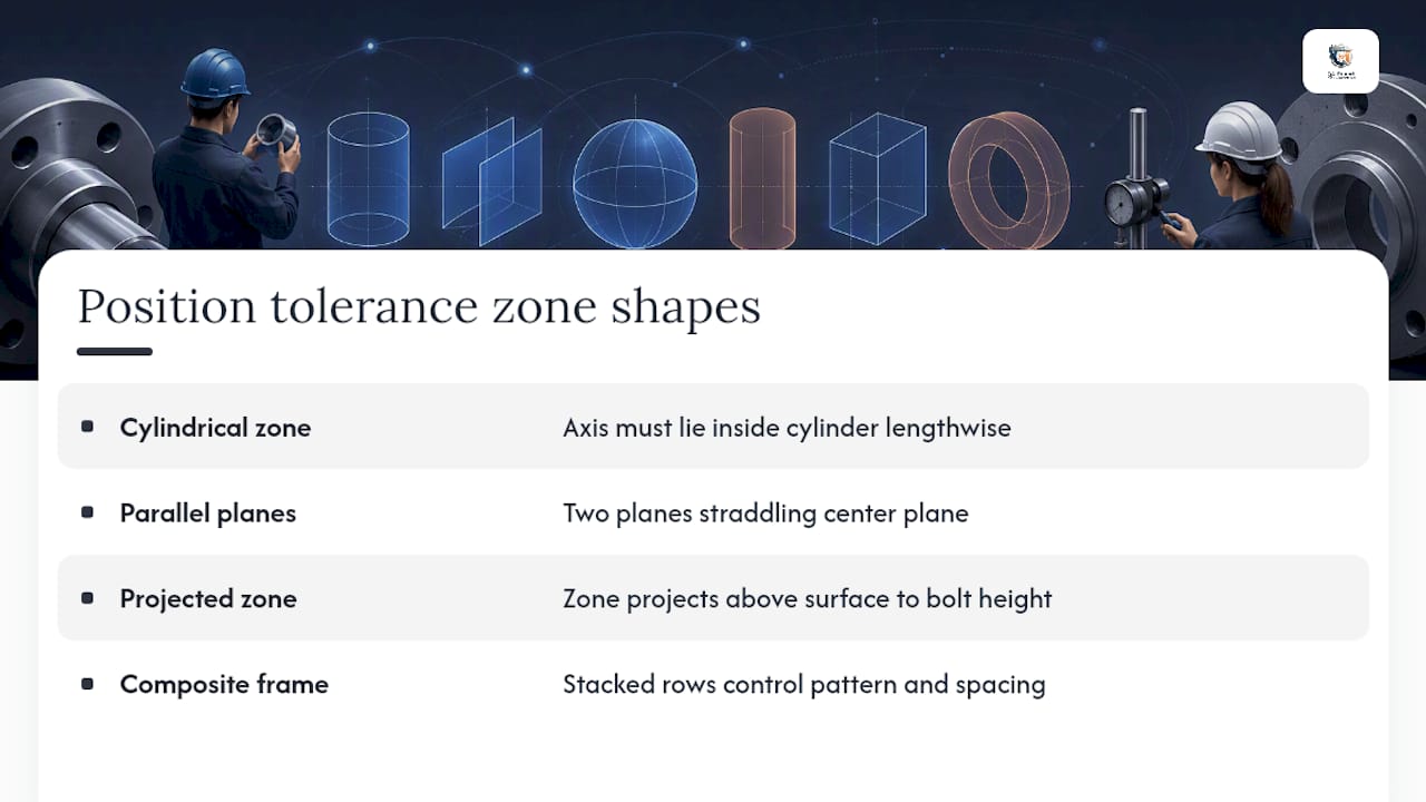
The position tolerance zone for a hole or pin is a cylinder, oriented perpendicular to the primary datum and centered on the true, theoretically exact location defined by the basic dimensions. Picture a perfectly straight tube of air running through the nominal center of the hole. The feature's actual axis, from top surface to bottom surface, has to stay inside that tube along its entire length. Compare that to a 2D square coordinate zone, which only checks a single point in a single plane and says nothing about tilt through the material's thickness.
For a slot or a feature controlled by a center plane rather than an axis, the "zone" becomes two parallel planes instead of a cylinder, spaced apart by the tolerance value, straddling the nominal center plane.
Projected tolerance zones come into play when the feature being located is threaded, or when a pin or dowel will extend some distance beyond the part's surface. Rather than controlling the axis where it sits inside the hole, the zone gets projected outward, above the part surface, to the height a mating fastener or pin would actually occupy. This matters because a threaded hole that's perfectly straight where the thread engages can still tilt enough over the length of a long bolt to bind the joint. You'll see a projected zone flagged in the feature control frame with a boxed height value and the ⊕ modifier, telling the inspector exactly how far above the surface the projection extends.
Composite and multiple-segment position tolerances solve a different problem: a pattern of holes that needs a loose tolerance to a distant datum (say, the overall part outline) but a tight tolerance to each other (say, the spacing within the pattern itself). A composite feature control frame stacks two or more tolerance rows under one position symbol, where the upper row controls the pattern's location and the lower row or rows control the pattern's internal spacing, often at a tighter value. This is common on multi-hole flange patterns and connector arrays, where the bolt circle's overall position matters less than the holes lining up with each other.
When you're inspecting against any of these zones, visualize the actual physical shape you're checking against, not just a number on a printout. A cylinder means checking the axis's full length, not one probe hit near the surface.
Why Do Datum Selection and Feature Shift Matter?
Datum reference frames establish the coordinate system that true position is measured against, and get the datum sequence wrong and every downstream position calculation is measuring against the wrong origin. ASME Y14.5 requires datums to be listed in priority order in the feature control frame, primary, secondary, then tertiary, and each one constrains a specific set of degrees of freedom. Choosing datums that don't reflect how the part actually functions in its assembly, discussed in more depth in why fixtures and GD&T sometimes disagree, is one of the most common root causes of parts that measure "bad" on a CMM but assemble just fine on the floor.
Datum feature shift happens when a datum feature itself carries an MMC or LMC modifier and its actual size departs from that condition. The part gets to "shift" within the gage or fixture that represents the datum, within the clearance created by that departure, before you evaluate position. It's the same bonus-tolerance logic applied to the datum instead of the feature being measured, and skipping it is a quiet way to fail parts that would actually pass with proper alignment.
Functional gaging puts this theory into physical form. At MMC, a functional gage represents the virtual condition, the worst-case combination of size and position a feature could have and still assemble. For a hole under MMC position, the pin gage diameter is calculated as:
Gage pin Ø = Hole MMC size − Position tolerance
A part passes the functional gage simply by accepting the pin. No coordinates, no arithmetic, just go/no-go. Fixed gaging like this is fast and consistent for high-volume production, though it tells you pass/fail without telling you by how much, which is where CMM data and proper CMM data import into your inspection reports earns its value for process improvement.
Pro Tip: Design datum features to be gage-friendly from the start, generously sized, accessible, and free of interrupted surfaces. A datum feature that's hard to probe consistently will produce inconsistent position results no matter how good your gage is.
What's the Right Workflow for Inspecting Position on a CMM?
Inspecting position tolerance reliably comes down to controlling the setup before you ever touch the part with a probe. A CMM workflow that skips alignment steps will produce numbers that look precise and are quietly wrong.
- Secure and stabilize the part. Use fixturing that supports the part the same way its datums are defined on the drawing, not just however it happens to sit flattest on the table. Custom 3D-printed part-holding fixtures can solve this cheaply for irregular geometry.
- Establish the datum reference frame first. Probe the primary datum surface to set the reference plane, then the secondary and tertiary datums in order, exactly matching the sequence in the feature control frame.
- Probe the feature of size. For a hole or boss, take enough points around the circumference (typically four or more, spaced evenly) to fit an accurate circle and derive the axis, not just a single diameter reading.
- Extract the feature's actual center coordinates in the established datum coordinate system, not in machine coordinates.
- Calculate Δx and Δy against the basic dimensions, then run the TP formula.
- Apply bonus tolerance, if an MMC or LMC modifier applies, using the feature's measured actual size.
- Log the result against the total allowed tolerance and flag pass/fail automatically if your software supports it.
For simpler jobs or lower-volume shops, manual inspection still has a place. A comparator or dial test indicator against a fixed reference can verify position on parts with generous tolerances or non-critical features, though manual methods struggle to capture true 3D axis deviation the way a CMM does, and they're a poor fit for anything with a tight bonus-tolerance calculation riding on it.
A few coordinate-transform habits separate clean data from disputed data:
- Never mix machine coordinates with part coordinates in the same report. Always transform to the datum reference frame before calculating deviation.
- Re-verify alignment if the part is unclamped and reclamped mid-inspection; even a fixture that looks identical can introduce a fraction of a degree of rotational bias.
- Watch probe compensation settings. An incorrect stylus tip radius offset shifts every reading in a hole pattern by the same systematic amount, which can look exactly like a real position error.
- Note environmental conditions, temperature drift on a large aluminum part between measurement points can introduce deviation that has nothing to do with the machining process.
For repeatability, document your sampling plan, fixture setup, and any environmental notes alongside the numbers themselves. If your facility is running a high volume of similar inspections, it's also worth periodically revisiting how many CMMs your inspection capacity actually needs against your throughput, since a bottleneck at the CMM often shows up first as inspectors cutting corners on setup steps to keep pace.
What Belongs in a True-Position Inspection Report?
A true-position result is only as trustworthy as the paper trail behind it. An auditor, or an engineer trying to root-cause a failure six months later, needs to see the same numbers you used to make the call, not just a stamped "pass."
Run through this checklist before signing off on a position inspection:
- Confirm the fixture setup matches the datum reference frame specified on the drawing, not a convenient substitute.
- Verify each datum surface individually before probing the feature itself.
- Capture the feature's actual size along with its location, since you need both for any MMC bonus calculation.
- Run the Δx/Δy and TP calculation, and record the intermediate numbers, not just the final result.
- Check the total allowed tolerance, base tolerance plus bonus, before making the pass/fail call.
- Cross-check against a functional gage where one exists, especially for high-volume or safety-critical features.
A complete report should include the drawing reference and revision, the exact feature control frame as written, measured coordinates, computed TP, any bonus tolerance applied and the actual feature size that generated it, the final pass/fail decision, the inspector's name, and the date. For regulated industries, keep the supporting artifacts too: probe logs, the CMM program version used, fixture photos if the setup is non-obvious, and traceable calibration certificates for any gages involved. These are exactly the fields that turn a spreadsheet into an audit-ready record instead of a number someone has to defend from memory later.
What Do Experienced Inspectors Watch For?
Datum selection causes more spurious position failures than measurement error does. An inspector who picks a convenient clamping surface instead of the drawing's actual primary datum will generate numbers that look like a process problem when it's really a setup problem. That single habit, verifying the datum sequence before touching the feature, resolves more disputed rejections than any amount of re-measuring.
The second recurring mistake is treating every failure as a machining problem. Sometimes a part fails position because the tolerance itself doesn't reflect how the assembly actually behaves, particularly on legacy drawings where a tight number got copied forward from a similar part without anyone checking whether MMC would be appropriate. Before pushing a supplier to tighten a process, check whether loosening the callout with a properly justified MMC modifier would serve the design intent just as well.
Process capability studies earn their keep here. If a feature consistently sits near the tolerance boundary across many parts, that's a capability conversation, not a one-off rework ticket.
Where Inspection Software Fits Into Position Tolerance Checks
Manual TP calculation works fine for a handful of features on a prototype run. It stops scaling the moment you're checking dozens of holes across hundreds of parts a week, especially in aerospace, automotive, or medical device production where every deviation needs a paper trail.
QA-Report handles the parts of this workflow that eat the most inspector time. The measurement wizard links ballooned drawing dimensions directly to measured results, runs the true-position calculation automatically, and applies MMC bonus tolerance based on the feature's actual measured size rather than leaving that math to a spreadsheet formula someone has to remember to update. CMM data import pulls coordinate data straight from your measurement equipment instead of retyping it, and automatic drawing ballooning removes the manual step of numbering every dimension on a PDF before inspection even starts.
Reach for a tool like this once you're inspecting position tolerance at volume, working in a regulated industry that demands traceable records, or tired of defending a "fail" call because nobody can find the intermediate Δx/Δy numbers from three weeks ago. QA-Report generates the audit-ready PDF automatically, with the calculation shown, not buried. If you're evaluating whether your current process could use that kind of automation, the measurement wizard and CMM import features are worth a look before your next high-volume inspection run.
Where to Verify These Rules and Calculations
Position tolerance rules ultimately trace back to one document, and everything else is interpretation built on top of it.
- ASME Y14.5 is the governing standard for GD&T in the United States, and it's the final word on datum reference frames, material-condition modifiers, and position rules whenever a drawing dispute needs resolving.
- GD&T Basics: True Position offers a clear, practitioner-oriented breakdown of the calculation method and worked examples.
- Engineers Edge True Position Calculator lets you verify a manual calculation against a validated tool before you commit to a pass/fail call.
- Geotol's Position Symbol Reference covers functional gaging and virtual condition formulas in more depth than most primers.
Frequently Asked Questions
What's the difference between position tolerance and true position?
They describe the same control from two angles. Position tolerance is the GD&T symbol and callout on the drawing, ⌖ with its tolerance value and datum references. True position is the calculated result, the actual diametral deviation you measure and compare against that stated tolerance. In practice, engineers use the terms interchangeably, but true position specifically refers to the number you compute.
How is true position different from concentricity?
True position controls the location of a feature's axis or center relative to a datum reference frame, and it's inspectable using actual surface points, which is why it dominates modern drawings. Concentricity controls the median points of a feature relative to a datum axis, a control that's notoriously difficult to measure directly because it requires finding the midpoint between opposing surface points at multiple cross-sections. Most drawings that once specified concentricity are better served by position or profile tolerance today, precisely because those controls are measurable with standard CMM techniques.
Can position tolerance apply to a slot instead of a hole?
Yes. For a slot or a feature controlled by a center plane, the tolerance zone becomes two parallel planes straddling the nominal center plane instead of a cylinder around an axis. The calculation logic is the same, deviation from nominal, compared against the stated tolerance, just applied to a planar zone instead of a cylindrical one.
What happens if a feature control frame has no datum references at all?
A position callout without datums is incomplete under ASME Y14.5 and shouldn't pass drawing review. Position tolerance only makes sense relative to a defined origin. Without a datum reference frame, there's no way to establish where the "theoretically exact location" actually sits, and inspectors have no consistent basis for measurement.
Do I need a CMM to check position tolerance, or can I do it manually?
A CMM gives you the most reliable axis extraction, especially for tight tolerances or features with bonus tolerance riding on accurate size measurement. Manual methods, comparators, dial indicators, or fixed pin gages, work fine for looser tolerances or high-volume go/no-go checks, but they generally can't capture the same depth of data for troubleshooting a marginal or failing result.
Why Position Tolerance Gets Misapplied More Than It Gets Misunderstood
Most engineers understand the concept of position tolerance well enough. Where things break down is application: choosing the wrong datum sequence, forgetting to check whether MMC would actually help manufacturability, or treating a borderline TP calculation as a definitive pass without questioning gage repeatability first.
The conventional advice is to tighten tolerances when parts keep failing. That's often backward. A callout that ignores available clearance, by skipping an MMC modifier that the design intent would clearly support, manufactures scrap that would assemble perfectly fine. The better first move is almost always to ask whether the tolerance itself reflects how the part functions, before assuming the process is broken.
The other underrated habit: showing your math. A pass/fail stamp with no Δx/Δy behind it is a liability the moment someone questions the result. Reports that expose the intermediate calculation, not just the verdict, are what actually resolve disputes between engineering and the inspection floor, and that transparency matters more for building trust in a quality system than any single tightened tolerance ever will.
Sources
- ASME Y14.5 — Dimensioning & Tolerancing
- True Position - Position Tolerance
- True Position - Measured Offset Calculator