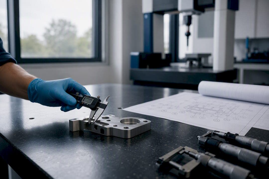
For manufacturing, assemblies, and any file carrying product manufacturing information (PMI), request STEP, specifically AP214 or AP242. Reserve IGES for cases where a legacy importer explicitly demands it, or for pure surfacing work where solid topology doesn't matter. That's the whole decision tree for most quality and CAD teams, and everything below explains why.
STEP, formally ISO 10303, was built to replace IGES's information loss with a structured, extensible exchange standard. QA-Report's own CAD viewer and inspection workflows are built around that reality: STEP files carry the geometry, structure, and often the tolerancing data your inspection reports depend on, while AS9102 and PPAP still treat the 2D drawing as the legal record of tolerances regardless of which 3D format you send.
- Always ask for native + STEP when the part is going into machining, CMM inspection, or an assembly with mated parts.
- IGES is acceptable only for legacy CNC/CAM systems that reject STEP outright, or for surface-only geometry transfer where solids aren't required.
Key Takeaways
STEP (particularly AP214 and AP242) is the manufacturing-ready standard for solids, assemblies, and PMI, while IGES survives only as a legacy fallback for surface-only exchange.
| Point | Details |
|---|---|
| Default to STEP | Request AP214 or AP242 for any part involving CAM, CMM, or assembly work. |
| Reserve IGES for legacy needs | Accept it only when a system explicitly rejects STEP or for pure surfacing tasks. |
| Never trust conversion alone | Converting between formats can't recover lost design intent or parametric history. |
| Drawings still govern tolerances | Keep a ballooned PDF as the controlling document for AS9102 and PPAP compliance. |
| Verify before you trust the geometry | QA-Report's CAD viewer and ballooning tools let teams check STEP and IGES models against inspection requirements in one workflow. |
Table of Contents
- STEP vs IGES: The Technical Comparison Engineers Actually Need
- What Is STEP and Why Do the AP Numbers Matter?
- When Is IGES Still the Right Format to Use?
- How Do You Avoid Conversion Errors Between STEP and IGES?
- A Simple File Policy Every CAD and QA Team Should Adopt
- Let QA-Report Turn Your STEP Files Into Audit-Ready Inspection Reports
- Frequently Asked Questions
- Sources
STEP vs IGES: The Technical Comparison Engineers Actually Need
The differences between these formats aren't cosmetic. They affect whether a part imports as a usable solid or as a pile of surfaces someone has to rebuild by hand.
STEP preserves boundary representation (B-Rep) topology, meaning solids typically arrive as solids, with faces, edges, and vertices connected the way they were modeled. IGES, by contrast, was designed around independent surface and wireframe entities. It has no native concept of a watertight solid, which is why IGES imports commonly show up as disconnected surfaces requiring knitting or repair, while STEP files tend to arrive intact.
| Dimension | STEP (AP214/AP242) | IGES |
|---|---|---|
| Topology / B-Rep support | Preserves solid topology and connectivity | Surface and wireframe only, no native solids |
| Assembly & metadata | Supports assembly structure, colors, and PMI/GD&T (AP242) | No assembly hierarchy, no PMI |
| Industry adoption | Active standard, updated through AP242 | Development effectively stopped in the 1990s |
| Geometric accuracy | Generally robust, fewer repair steps | Prone to open shells, gaps, fillet failures |
| Typical uses | CAM, CMM, FEA, cross-CAD collaboration | Legacy systems, pure surfacing archives |
| Conversion risk | Lower, but still not a substitute for native files | Higher, frequent manual stitching required |
STEP's physical file format is defined by ISO 10303-21, a clear-text encoding scheme, so a .stp, .step, or .p21 file is technically readable but not something you'd want to parse by eye. It uses entity references that only make sense to a schema-aware viewer or CAD kernel.
A few practical implications follow directly from that table:
- STEP solids generally import into CAM software with fewer manual fixes than IGES surfaces.
- Shops frequently hold quotes when they receive IGES files that need reconstruction before programming can start.
- IGES is still fine for pure curve or surface data exchange where nobody needs a closed solid.
- Neither format substitutes for a native CAD file when someone downstream needs to edit features or history.
Pro Tip: Before sending any STEP file, confirm which AP version your export settings actually produced, most CAD packages default to an older AP unless you change it in the export dialog, and that single setting determines whether your PMI survives the trip.
What Is STEP and Why Do the AP Numbers Matter?
STEP stands for the Standard for the Exchange of Product model data, codified as ISO 10303. Files typically carry the .stp or .step extension, occasionally .p21 for the raw physical file. The standard isn't one monolithic format. It's a family of application protocols, each defining a different slice of product data.
AP203 covers basic geometric shape representation, solids and surfaces with minimal metadata. AP214 adds automotive-oriented data including colors, layers, and some assembly configuration management. AP242, the current focus of active development, unifies earlier protocols and adds model-based definition support, meaning GD&T and PMI can travel embedded in the file itself rather than living only on a 2D drawing.
In practice, STEP's strengths are B-Rep solid preservation, coherent assembly hierarchies, and broad support across CAM and FEA tools. Its limits are real, though. STEP carries no parametric feature history, so a recipient can't roll back to your sketch and edit a fillet radius. Exporters don't always include PMI even when the AP supports it. And because different CAD kernels translate geometry slightly differently, not every STEP file behaves the same way even under the same AP label, so file size and parsing complexity can vary between vendors.
- Confirm the AP version before exporting, don't assume your default settings include PMI.
- Test-open the exported file in a neutral viewer before sending it to a supplier.
Pro Tip: Ask your CAD administrator to set AP242 as the default export protocol for new projects, it's a one-time settings change that saves recurring back-and-forth with suppliers.
When Is IGES Still the Right Format to Use?
IGES dates back to the early 1980s, developed alongside the U.S. Air Force's ICAM initiative, and it saw its last major revision in 1996. It predates solid modeling as a mainstream CAD practice, which explains its architecture: IGES represents geometry as independent surfaces, curves, and wireframe entities rather than a connected solid body.
That geometry-only structure is the source of most IGES headaches. Surfaces that appear perfectly closed in the originating CAD system often import as unstitched patches elsewhere, particularly around fillets and freeform blends, which is why complex curved geometry is the most common failure point during IGES exchange.
IGES still earns its place in a few narrow situations: legacy CNC or CMM systems that only accept it, archived tooling data from decades-old projects, or surfacing-focused workflows where nobody needs a watertight solid. If you do accept an IGES file, verify the surfaces knit into a solid before treating the geometry as production-ready.
- Confirm the recipient's system genuinely can't accept STEP before defaulting to IGES.
- Run a knit/repair check immediately on import, don't assume the surfaces are closed.
- Treat IGES-derived solids as unverified until mass properties look correct.
Pro Tip: If a supplier asks for IGES "just to be safe," push back, ask them to test a STEP AP214 file first. Most modern systems handle it fine, and you'll skip the repair cycle entirely.
How Do You Avoid Conversion Errors Between STEP and IGES?
Converting a file from IGES to STEP, or the reverse, doesn't recover anything that wasn't there to begin with. Converters map geometric entities rather than reconstructing design intent, and the process can introduce new geometric errors on top of whatever the source file was already missing. If you need parametric history or embedded tolerances, the only reliable path is the native file plus a properly exported STEP, not a converted IGES.
Common failure modes worth knowing before you inspect an imported file:
- Open shells and gaps, usually from IGES surfaces that never stitched into a solid.
- Fillet and blend failures, where curved transitions don't reconstruct cleanly.
- Units or scale drift, when inch and millimeter settings mismatch between systems.
- Lost PMI and GD&T, when the exporter didn't include it or the importer ignores it.
- Topology differences from CAD kernel translation, even between two STEP files.
Run this checklist on any imported model before it enters your inspection workflow:
- Confirm body type: solid vs. surface, don't assume the file title tells the truth.
- Run a knit or repair operation and inspect for remaining gaps.
- Verify mass and inertia properties against the source model where available.
- Check for embedded PMI or GD&T, and cross-reference it against the drawing.
- Confirm units before recording a single measurement.
- Attach the native file and PDF drawing as the contract source of tolerances, since a 2D drawing remains the controlling document for AS9102 and PPAP compliance regardless of what the 3D file contains.
Pro Tip: Export in AP242 whenever your software supports it, keep native files archived indefinitely, and ask every new supplier which AP version their system reads before you send the first quote package.
A Simple File Policy Every CAD and QA Team Should Adopt
My honest recommendation is a two-line policy: always request native plus STEP AP242 or AP214, and accept IGES only when a system genuinely requires it, with a mandatory import verification step. Most disputes over "the file didn't match the part" trace back to skipping that verification, not to some exotic format quirk.
Build this into your RFQ template: specify naming conventions, units, required AP version, a PDF drawing, and a sample import check before committing to a precision laser cutting shop near Dacula, GA supplier relationship. Log every conversion failure and keep a native-file archive. It's your only real legal traceability when a dimension gets questioned months later.
Let QA-Report Turn Your STEP Files Into Audit-Ready Inspection Reports
Verifying a STEP file shouldn't mean opening three different tools before you can trust the geometry. QA-Report's built-in CAD viewer reads STEP and IGES models directly, so your team can check topology and dimensions in the same platform that generates the inspection report, instead of bouncing between a viewer, a spreadsheet, and a PDF.
Pair that with automatic drawing ballooning, and the workflow closes a gap most shops still handle manually: ballooned dimensions from your PDF link directly to measured CMM results, with out-of-tolerance values flagged automatically rather than caught during a final review. That matters most when you're juggling STEP files from five different suppliers, each exported with a different AP version and a different level of PMI reliability. For teams that want to see the ballooning workflow before committing to anything, QA-Report's free drawing ballooning tool is the fastest way to try it on a real drawing. When you're ready to connect that to full CMM import and AS9102 reporting, the QA-Report platform is where the rest of the workflow lives.
Frequently Asked Questions
Is STEP always better than IGES? For manufacturing, assemblies, and anything requiring PMI, yes. IGES still has a narrow role in legacy systems and pure surfacing work, but it's not a like-for-like competitor to STEP anymore.
Can I convert an IGES file to STEP and get full functionality back? No. Conversion maps geometry, it doesn't reconstruct design intent or parametric history, and it can introduce new errors depending on the converter and source file quality.
What's the difference between AP203, AP214, and AP242? AP203 covers basic solid and surface geometry. AP214 adds automotive-style metadata like colors and configuration management. AP242 is the current standard, supporting embedded PMI and GD&T for model-based definition workflows.
Do I still need a PDF drawing if I send a STEP file with PMI? Yes. Exporters don't always include PMI reliably, and AS9102/PPAP frameworks still treat the 2D drawing as the legal authority for tolerances.
Why does my IGES file show gaps or open surfaces after import? IGES has no native solid representation, so surfaces that appeared closed in the source system frequently import as unstitched patches, especially around fillets and blends.