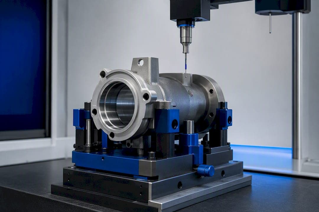
A datum reference frame (DRF) is the theoretically perfect coordinate system derived from datum features that all GD&T feature controls reference for inspection. It gives every measurement a fixed origin and orientation, so a hole position or surface profile means the same thing on the drawing, on the CMM, and on the shop floor. A DRF is built from primary, secondary, and tertiary datums, which together lock all six degrees of freedom.
TL;DR:
- Proper datum selection aligns with functional mating surfaces and ease of fixture, reducing inspection ambiguity and avoiding false rejects.
- Swapping datum order in feature control frames changes the measurement setup, potentially flipping parts from pass to fail.
- Using real fixtures like surface plates, V-blocks, and gauge pins ensures the simulated DRF closely matches the theoretical model.
- Early involvement of manufacturing and quality teams in datum decision-making leads to fewer RFIs and more reliable fixtures.
- Inspection software that links GD&T calls to measurements helps maintain consistent DRFs, reducing human error and resolving datum disputes.
Table of Contents
- What Does "Datum Reference Frame" Actually Mean?
- How Do Datums Constrain the Six Degrees of Freedom?
- Choosing Datum Features That Actually Work on the Shop Floor
- How Do You Simulate a Datum Reference Frame During Inspection?
- Why Do Parts Fail Inspection Over Datum Ambiguity?
- What Do Real Datum Reference Frame Examples Look Like?
- How Inspection Software Keeps Datum Reference Frames Consistent
- Why Datum Selection Deserves Design-Level Attention
- Reduce Datum Ambiguity With Connected Inspection Software
- Where to Read More on Datum Standards
- Sources
What Does "Datum Reference Frame" Actually Mean?
A datum, in ASME Y14.5 terms, is a theoretical point, axis, or plane. It's mathematically exact but physically doesn't exist. A datum feature is the real, tangible surface, hole, or edge on the part that you touch, clamp, or probe to establish that theoretical datum. This distinction trips up a lot of engineers early in their GD&T education, and it's worth internalizing: you never measure "to a datum." You measure to a datum feature and simulate the datum from it.
The DRF works like a coordinate system built specifically for that part, except it isn't arbitrary. It's derived from features chosen because they reflect how the part actually functions or assembles. You'll find the DRF referenced constantly on a drawing, even when the term never appears explicitly:
- Datum feature symbols (letters in boxes, like A, B, C) attached to specific surfaces or features.
- Feature control frames, where the datum letters appear in a specific order after the tolerance value.
- Basic dimensions, which locate features relative to that same reference frame.
How Do Datums Constrain the Six Degrees of Freedom?
Every rigid part in space has six degrees of freedom (DOF): three translations (X, Y, Z) and three rotations about those axes. The datum precedence in a feature control frame determines which datum removes which DOF, and the order is never arbitrary.
The classic 3-2-1 rule breaks it down this way:
- Primary datum contacts the part first and removes several degrees of freedom including translations and rotations.
- Secondary datum contacts next and removes additional degrees of freedom.
- Tertiary datum contacts last and removes the final degree of freedom to fully constrain the part.
Pro Tip: If you swap the datum order in a feature control frame, say from A|B|C to B|A|C, you're not relabeling the same measurement. You're defining a different physical setup, which can shift a feature's apparent position enough to flip a pass into a fail.
Choosing Datum Features That Actually Work on the Shop Floor
Datum selection is a design decision with manufacturing consequences, not a formality you fill in after the geometry is locked. Good datum features share three traits:
- They correspond to real functional mating surfaces, the faces or bores that actually control how the part sits in an assembly.
- They offer repeatable seating, meaning a fixture or gauge contacts them the same way every time.
- They're accessible for both fixturing and probing, so inspectors aren't reaching around obstructions to hit a CMM point.
Choosing datums based on assembly function, rather than convenience on the drawing, keeps the DRF aligned with actual design intent and makes inspection far less ambiguous downstream.
Datum targets come into play when a full feature can't serve as a reliable reference, an interrupted surface, a casting pad, or a feature with only limited usable contact area. Instead of calling out the whole face, you specify target points, lines, or areas with basic dimensions, tied to established tooling tolerances. Whether a feature functions as a "qualifying" datum immediately or needs additional setup steps also affects how fast a shop can move from part to measurement without guesswork.
How Do You Simulate a Datum Reference Frame During Inspection?
Simulating a DRF means recreating those theoretical datums with real equipment, closely enough that the measurement matches design intent. The most common simulators include:
- A surface plate with three-point contact for a primary planar datum.
- V-blocks for cylindrical or shaft-type primary or secondary datums.
- Gauge pins or blocks to establish secondary or tertiary contact points.
- CMM-constructed datum planes, axes, and points built directly from probed data.
On a CMM, the alignment routine has to reconstruct the same DRF the drawing specifies, in the same order, using the same feature types. Importing a STEP or IGES model alongside the physical part helps confirm that the programmed alignment matches the nominal geometry rather than an approximation built by eye.
One rule catches more inspectors off guard than any other: simultaneous requirements. When multiple feature control frames call out the same datums in the same order with the same modifiers, those features must be measured relative to the same DRF instance, in the same fixtured setup. Unclamp the part and re-fixture it between two "related" measurements, and you can invalidate the comparison entirely, even if each individual reading looks fine.
Why Do Parts Fail Inspection Over Datum Ambiguity?
Most datum-related rejections trace back to a handful of repeatable errors, and nearly all of them are avoidable with a second look before the drawing releases.
- Calling a full-face datum when only local contact exists. A casting or a part with ribs, bosses, or an uneven surface can't provide reliable full-face contact. The fix is datum targets, or a clarifying note that specifies exactly where contact occurs.
- Ignoring simultaneous requirements. If a CMM routine re-zeroes or re-fixtures between related features, program it instead to hold the DRF state, and flag simultaneous requirements explicitly in first article inspection (FAI) documentation.
- Choosing datums that are ambiguous in order or impossible to fixture. Impractical datum choices increase supplier quoting risk and generate a steady stream of RFIs. Cross-team review between design and quality, plus early fixture validation, catches this before it reaches the floor.
Pro Tip: When a supplier keeps asking the same clarifying question about a datum, that's rarely a supplier problem. It usually means the feature control frame itself is ambiguous, and rewriting the note solves it for every future job, not just this one.
What Do Real Datum Reference Frame Examples Look Like?
A prismatic block illustrates the 3-2-1 rule cleanly:
- Face A (the largest, most stable face) becomes the primary datum, seated flat on a surface plate, removing 3 DOF.
- Side B, pushed against a locating pin, becomes the secondary datum, removing 2 more DOF.
- Edge C, contacted by a single stop, becomes the tertiary datum, removing the last DOF.
Once that DRF exists, basic dimensions and feature control frames on holes or slots reference A|B|C, and the position tolerance is measured relative to that exact setup.
A flange or shaft works differently. Instead of three flat faces, the primary datum is often a bore's axis (an internal cylindrical feature), with a face as secondary and a keyway or hole as tertiary to lock rotation. Where the flange has interrupted contact, such as a bolt circle with gaps, datum targets on specific pad locations replace a continuous face callout, keeping the DRF physically achievable.
How Inspection Software Keeps Datum Reference Frames Consistent
A DRF only works if design, manufacturing, and quality are all measuring against the identical setup, and that's precisely where paper-based inspection breaks down. QA-Report's automatic drawing ballooning links each GD&T callout directly to its measured result, cutting down the mislabeling that creates datum confusion in the first place.
- CMM import and tolerance validation confirm the same DRF instance is used across every related measurement, not a slightly different alignment run by a different inspector.
- Audit-ready FAI reports preserve the fixtured state tied to simultaneous requirements, so compliance reviewers see exactly how the part was held when it was measured.
Why Datum Selection Deserves Design-Level Attention
Datums get treated as a drawing afterthought too often, added after geometry is frozen instead of during concept review. That habit is backwards. Bringing manufacturing and quality into datum decisions early, before the model is locked, consistently produces fewer RFIs, fewer false rejects, and fixtures that actually match the print.
— Michael Chen
Reduce Datum Ambiguity With Connected Inspection Software
QA-Report closes the gap between a drawing's datum reference frame and what actually happens at the CMM or fixture, something spreadsheets and disconnected PDF markups were never built to enforce.

The platform's ballooning tool maps every GD&T callout to its measured value automatically, while CMM data import and tolerance validation confirm the measurement DRF matches the one on the print, not an approximation. FAI reports generated through the platform document the fixtured state behind every simultaneous requirement, giving auditors a clear record instead of a guess. For a deeper look at how physical datum features differ from inspection equipment behavior, the guide from Symmnet on manufacturing data workflows is a useful companion read. If your team is still reconciling datum interpretation disputes over email, start a trial and run one part through the CMM inspection workflow to see where the ambiguity actually lives.
Where to Read More on Datum Standards
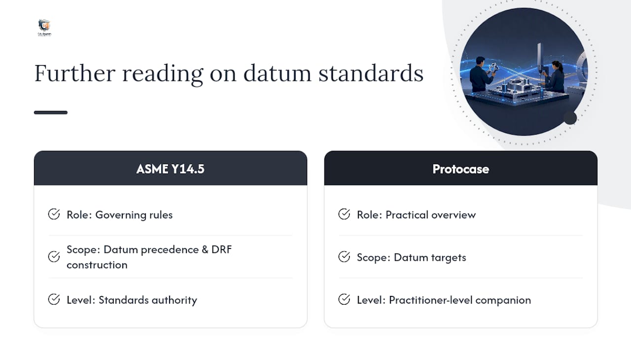
For the governing rules on datum precedence and DRF construction, read ASME Y14.5 directly. The Protocase overview of datum targets offers a practical, practitioner-level companion.