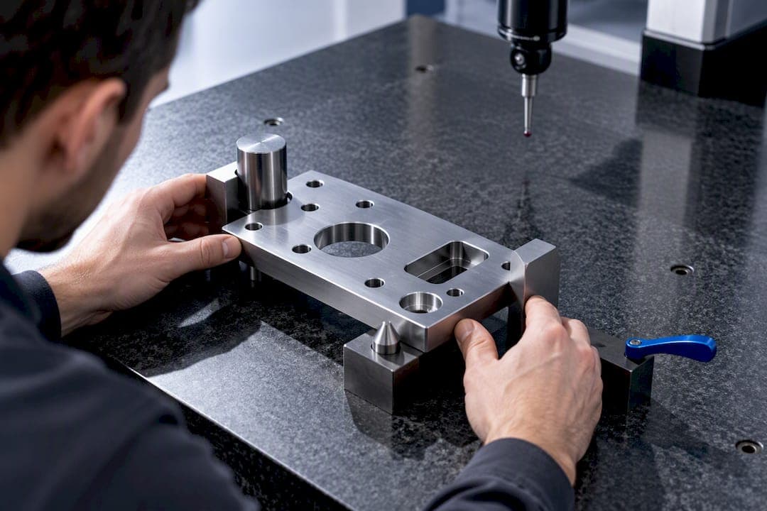
In GD&T, a datum is a theoretical point, axis, or plane that serves as the origin for every geometric tolerance applied to a part. Datum features are the real, imperfect physical surfaces used to establish that theoretical origin. Choosing the right datums, and setting them up correctly on a CMM or fixture, determines whether your inspection results actually reflect how the part functions in an assembly.
TL;DR:
- Using the wrong type of datum simulator or failing to record its specifics can cause inconsistent measurement results and misinterpretation of part functionality.
- Selecting datum features that reflect the actual mating or assembly surfaces ensures that inspection results accurately predict real-world part performance.
- Distinguishing between RMB and MMB material conditions is critical, as ignoring datum shift from fixed MMB simulators can lead to false rejects or overlooked acceptance.
- Proper sequence and setup of datums following the 3-2-1 rule are essential to lock the part's degrees of freedom and achieve reliable measurement referencing.
- Confirming the fitting algorithm used by the CMM and validating fixture stability reduces errors caused by software or hardware misconfigurations.
Table of Contents
- Datums, Datum Features, and the Datum Reference Frame Explained
- Datum Feature Simulators and the True Geometric Counterpart
- Choosing Between Surface, Axis, and Target Datums
- How to Pick Datums That Actually Reflect Function
- RMB, MMB, and Why Datum Shift Catches Teams Off Guard
- Setting Datums on the Shop Floor: CMM and Fixture Practice
- Standards Context: ASME Y14.5 and Constrained Least-Squares
- How QA-Report Fits Into a Datum-Based Inspection Workflow
- Where Most Datum Mistakes Actually Come From
- Try a Datum-Based Inspection Workflow in QA-Report
- Sources
- FAQ
Datums, Datum Features, and the Datum Reference Frame Explained
A datum exists only in theory. It is the perfect point, line, or plane that a real surface approximates but never fully matches. The physical surface used to derive that theoretical datum is called a datum feature, and the distinction matters more than it sounds: you measure from the datum, not from the datum feature itself, which is why an imperfect physical surface establishes an idealized reference rather than serving as the reference itself.
When a drawing calls out three datums, usually labeled A, B, and C, they combine to form a datum reference frame, or DRF. Each datum in the sequence removes degrees of freedom from the part:
- The primary datum contacts at three points and removes three degrees of freedom, typically rotation about two axes and translation along one.
- The secondary datum contacts at two points and removes two more degrees of freedom.
- The tertiary datum contacts at one point and removes the final degree of freedom, locking the part in space.
This sequence, often called 3-2-1 locating, is why datum order on the feature control frame is never arbitrary. Swap datum B and datum C and you get a mathematically different, and often functionally wrong, reference frame.
Datum Feature Simulators and the True Geometric Counterpart
The theoretical datum has to come from somewhere physical during inspection, and that is the job of the datum feature simulator: a surface plate, a precision mandrel, a collet, or a set of expanding pins that stands in for the perfect geometry the drawing calls out. The simulator's contact surface is called the true geometric counterpart, and it is this idealized counterpart, not the part's actual imperfect surface, that becomes the measurement origin. A datum feature simulator establishes the true geometric counterpart used to derive the datum during measurement.
- A flat surface plate simulates a planar primary datum.
- An expanding mandrel or collet simulates a cylindrical datum feature of size.
- A set of precision pins can simulate a pattern of holes acting together as one datum.
This is also where inconsistent readings often start. Two labs using different simulator hardware, or different collet expansion ranges, can produce different results from the same part.
Pro Tip: Record the exact simulator type and size used for each datum feature in your inspection report, not just the nominal datum callout.
Choosing Between Surface, Axis, and Target Datums
Not every datum feature is a flat surface or a bore. Large, irregular, or partially formed parts often need datum targets instead of full-surface datums, and picking the wrong type creates fixtures that are expensive, unrepeatable, or both.
- Planar datums work for machined faces, mounting flanges, or any broad, accessible surface that can sit flush against a simulator.
- Axis datums apply to bores, shafts, and bosses, established with a mandrel or expanding collet as the true geometric counterpart.
- Datum targets (points, lines, or areas) locate large or warped panels, castings, and sheet metal where a full surface contact is impractical or unrealistic.
A large composite assembly panel, for example, might use a 3-2-1 target scheme: three point targets on the primary face, two on an edge for secondary alignment, and one final point to lock rotation, instead of demanding flush contact across an entire warped surface.
How to Pick Datums That Actually Reflect Function
The most common datum mistake is choosing references that are convenient to machine rather than references that reflect how the part mates in the final assembly. A datum reference frame must simulate the functional assembly, or the gage can pass a part that will not actually fit or perform correctly downstream.
Run through this before finalizing datum selection:
- Does the datum surface correspond to the actual mating or contact surface in assembly?
- Can the datum be measured repeatably across parts, operators, and fixtures?
- What does the fixture or gage cost to build and maintain against this datum scheme?
- Are critical interfaces (bearing bores, mounting faces, sealing surfaces) given priority as primary or secondary datums?
Manufacturing convenience sometimes wins for good reason: a functional datum that requires a custom fixture for every part run may not be worth the cost if a manufacturing datum gives equivalent results. When that trade-off happens, document why, and confirm the substitute datum still constrains the same critical degrees of freedom. Our guide on misaligned datums and fixtures walks through what goes wrong when this check gets skipped.
Pro Tip: When converting a functional datum into a manufacturing datum, verify the substitute still controls the same degrees of freedom, not just the same nominal location.
RMB, MMB, and Why Datum Shift Catches Teams Off Guard
Datum features of size (bores, bosses, slots) can be referenced two ways: regardless of material boundary (RMB) or at maximum material boundary (MMB). Under RMB, the simulator adjusts to fit the actual part, expanding or contracting to make contact, so there is no datum shift. Under MMB, the simulator is fixed at the worst-case boundary size, and practitioners must distinguish RMB simulators that adjust from MMB simulators that stay fixed.
That fixed MMB simulator is what creates datum shift: extra positional tolerance the part effectively gains as its actual size departs from the MMB boundary.
- RMB simulators (expanding collets, adjustable pins) conform to each part, so datum location varies part to part but no shift bonus applies.
- MMB simulators (fixed gage pins) stay at one size, and any part smaller than that boundary can shift within the simulator, changing how position tolerance stacks up.
- Ignoring this distinction is a frequent cause of false rejects, where a part is functionally acceptable but measured against the wrong simulator behavior.
When a datum feature of size departs from maximum material condition under RMB, the simulator itself changes size to match, which is why a datum feature simulator's behavior, not the part's nominal geometry, determines measurement repeatability.
Metrology teams should confirm the material condition modifier on every datum feature of size before programming a CMM routine, since an RMB part measured with MMB assumptions (or the reverse) produces results that look wrong even when the part is fine.
Setting Datums on the Shop Floor: CMM and Fixture Practice
Getting the theory right on a drawing means little if the physical setup does not match it. A consistent process protects both repeatability and audit readiness.
- Build the DRF in CMM software in the drawing's exact A-B-C order, never in a convenient probing sequence.
- Run a shim test or repeatability check by remeasuring the same part multiple times and across operators to confirm the simulator contact is stable.
- Validate the fixture against the true geometric counterpart it is meant to simulate, checking wear on pins, collets, or plates that see high part volume.
- Document the simulator type, size, and material condition for every datum feature directly in the inspection report, not in a separate setup sheet.
- Import CMM measurement data directly into your report software rather than retyping values, which cuts transcription errors and keeps ballooned drawing numbers tied to measured results.
A workflow that links automatic drawing ballooning to CMM data import removes a lot of the manual re-entry where datum and dimension mismatches tend to creep in.
Standards Context: ASME Y14.5 and Constrained Least-Squares
ASME Y14.5 has moved toward more stable, well-defined datum establishment for digital metrology, reintroducing the term true geometric counterpart and favoring default stabilization over ambiguous candidate datum sets for unstable features. Underlying that shift is a mathematical approach called constrained least-squares. Standards committees are considering constrained least-squares as a mathematical definition for datums because it keeps the fitted datum surface outside the material boundary, avoiding the flip-flop behavior seen with some Chebyshev or shifted least-squares fits.
- Ask your CMM software vendor which fitting algorithm it applies to datum features by default.
- Confirm whether the algorithm documentation references constrained least-squares or an older, potentially unstable fitting method.
- Treat unexplained variation between repeated measurements of the same datum as a sign the fitting algorithm, not the part, may be the problem.
How QA-Report Fits Into a Datum-Based Inspection Workflow
A typical workflow starts with a ballooned drawing, moves through CMM measurement, and ends in a report someone has to trust. QA-Report's CMM data import maps measured values to ballooned dimensions automatically, including datum-referenced features, then flags out-of-tolerance results before the report is generated. Combined with the built-in 3D CAD viewer for checking datum feature locations against the STEP or IGES model, the output is a PDF report structured to satisfy ISO 9001, AS9100, or PPAP documentation requirements.

Where Most Datum Mistakes Actually Come From
Most datum errors I see trace back to convenience, not ignorance: a fixture built around what is easy to machine rather than what the assembly actually needs, or a CMM programmed without confirming which fitting algorithm it uses. Validate the fixture, tie datums to function, and check the software before trusting the numbers.
— Michael Chen
Try a Datum-Based Inspection Workflow in QA-Report
Getting datums right on paper is one thing. Keeping that accuracy through CMM import, ballooning, and a final PDF report is where most teams lose hours to manual re-entry and version mismatches. The measurement wizard links ballooned drawing dimensions directly to measured results, auto-flags anything out of tolerance, and produces statistical summaries built for ISO 9001, AS9100, and PPAP submissions.

If your team wants to see how a datum-referenced dimension flows from drawing to finished report, the Free plan costs $0 per month and gets you into the platform without a commitment. The Basic plan runs $49.99 per month, and PRO is $149.99 per month for teams that need the full CMM import and MES layer. Run one datum-heavy part through the sample workflow and see how the report holds up against your current process.
Sources
- Datums, features and simulators — GD&T Basics
- Toward a new mathematical definition of datums in standards to support advanced manufacturing
- Datum feature simulators — Open Exam Prep (ASME/GD&T study guide)
FAQ
What is the 3/2/1 rule in GD&T?
The 3-2-1 rule describes how a primary, secondary, and tertiary datum remove degrees of freedom in sequence: three points of contact on the primary datum, two on the secondary, and one on the tertiary, for six total. This sequence locks the part in space for measurement and must follow the order specified in the feature control frame.
What are the three types of datum?
Datums are generally categorized as planar (flat surfaces), axis or cylindrical (bores, shafts, bosses), and datum targets (points, lines, or areas used on large or irregular surfaces). The right type depends on part geometry and how the surface will realistically contact a simulator during measurement.
Can you explain GD&T in a simple way?
GD&T defines how much a part's form, size, and location can vary while still functioning correctly in its assembly, using standardized symbols instead of written notes. Datums are the reference points, axes, or planes that every other tolerance measures from, similar to the zero point on a ruler.
Does position tolerance need three datums?
Position tolerance often references a full datum reference frame of three datums (primary, secondary, tertiary) to fully constrain the feature's location and orientation. Some callouts use fewer datums when the feature does not require full six degree of freedom control, so the actual requirement depends on what the drawing specifies.
What is a datum feature simulator?
A datum feature simulator is the physical tooling, such as a surface plate, mandrel, or collet, that represents the true geometric counterpart of a datum feature during inspection. Measurements are taken from this simulator rather than from the part's actual imperfect surface, which is why documenting the simulator used is critical for repeatable results.