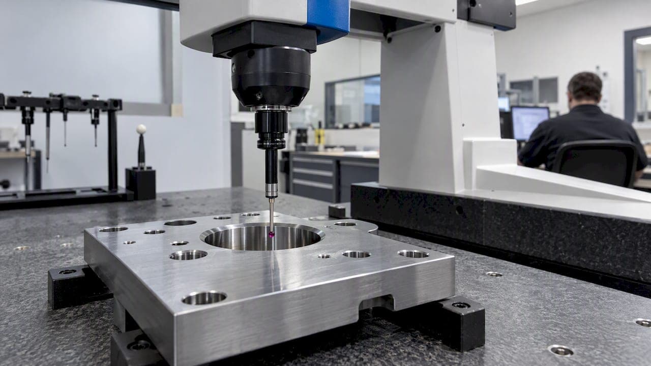
MMC (maximum material condition) is the state with the most material, and LMC (least material condition) is the state with the least. Use MMC to guarantee assembly, and use LMC to guarantee minimum material, such as wall thickness. Both modifiers let a geometric tolerance grow as a feature departs from its worst-case size, which changes how parts are designed and inspected.
TL;DR:
- Rule #1 requires perfect form at the MMC size, while an MMC or LMC modifier applies only one functional boundary to a feature.
- Calculate bonus as measured size minus the hole’s MMC limit, or the shaft’s MMC limit minus measured size, then add it to geometric tolerance.
- For every modified feature, inspectors should record size and position together; reports should include the bonus, total allowance, and pass or fail result.
- Use LMC when a hole’s largest size could threaten minimum wall thickness near an edge; use RFS when function does not depend on feature size.
- When assembly fit and minimum wall thickness both matter, assign the protections to separate features or calculate virtual and resultant conditions.
Table of Contents
- What MMC and LMC mean for holes and shafts
- How Rule #1 and the modifiers shape the envelope
- Bonus tolerance, virtual condition, and how to calculate them
- Practical examples: pins, walls, and stacked features
- What changes at inspection
- A short checklist for choosing MMC or LMC
- Why the modifier should follow function
- How we help teams validate MMC and LMC faster
- FAQ
- Sources
What MMC and LMC mean for holes and shafts
Every feature of size has both conditions, and which size counts as which depends on whether the feature is internal or external. GD&T Basics explains this with a donut analogy, and JEDEC defines MMC as the condition holding the maximum amount of material.
- MMC for a shaft is its largest diameter. MMC for a hole is its smallest diameter.
- LMC for a shaft is its smallest diameter. LMC for a hole is its largest diameter.
- Modifier symbols in a feature control frame are Ⓜ for MMC and Ⓛ for LMC. Without a modifier, RFS applies, and the tolerance never grows.
For a hole, MMC is its smallest allowed diameter and LMC is its largest. For a shaft, MMC is its largest allowed diameter and LMC is its smallest.
How Rule #1 and the modifiers shape the envelope
Rule #1, the envelope principle, says that form is controlled by the limits of size. The ASME Y14.5 handbook documents this rule along with the definitions and decision diagrams for applying RFS, MMC and LMC. In practice, the rule sets a boundary you cannot cross.
- Perfect form at MMC is the implicit boundary. A feature at its MMC size must have perfect form, so bow or taper cannot push a pin past the limit that assembly depends on.
- Assembly protection follows from this. At worst-case material, the mating parts still fit.
- LMC-based control shifts the emphasis. The GD&T Basics discussion of Rule #1 notes that applying LMC moves the functional boundary to the least material size, which suits minimum wall thickness.
- One envelope only can govern a feature. As GD&T Basics explains on designing to MMC and LMC, you constrain form to one boundary, not both.
Bonus tolerance, virtual condition, and how to calculate them
A bonus tolerance is extra geometric tolerance earned as a feature moves away from MMC or LMC. Autodesk's reference on material condition modifiers describes the bonus as the difference between the measured size and the MMC or LMC limit. Virtual condition is the worst-case boundary produced by combining the size limit with the stated geometric tolerance.
- Identify the nominal size and its limits from the drawing.
- Find the MMC or LMC limit that the modifier references.
- Measure the actual size of the feature.
- Subtract: the distance from that limit is the bonus.
- Add the bonus to the stated geometric tolerance to get the allowable total.
Worked example (illustrative values): a hole has a position tolerance at MMC. Its bonus is the difference between its measured size and its MMC limit, which is added to the stated geometric tolerance to determine the total positional allowance.
The bonus is the measured size minus the MMC limit for a hole, and the MMC limit minus the measured size for a shaft. Software handles internal and external features differently, so confirm which case you are in.
Practical examples: pins, walls, and stacked features
Two scenarios show why the choice of modifier matters.
- Hole and pin assembly: a pin must enter a mating hole. Applying MMC to both guarantees the fit at worst-case material, and any size departure from MMC gives back positional room that makes parts easier to accept.
- Hole near an edge: a hole too close to an edge leaves a thin wall. Applying LMC to the hole's position protects the minimum material between the hole and the edge, because the hole at its largest size is the case that threatens the wall.
- Multiple interacting features: when several features stack, each virtual condition contributes to the worst-case boundary. Resultant condition calculations help when assembly and wall thickness concerns both exist.
- Alternative strategies: if one feature needs both protections, separate the functions across features rather than forcing two modifiers onto one.
Pro Tip: Write the virtual condition next to every modified feature on your working copy of the drawing. Inspectors and designers then argue about the same number.
Wall thickness concerns often start in design for manufacturability. A practical read on hole-to-edge distances and sheet metal DFM shows why edge distance deserves a dimension of its own, and the feature control frame on your drawing should state the modifier clearly, as our guide to reading the feature control frame describes.

What changes at inspection
When a modifier appears in the frame, size and position can no longer be judged independently. A part can pass at one size and fail at another with the same positional error, so inspectors must record both values.
- Measured size must be captured for every modified feature, since the bonus derives from it.
- CMM software typically calculates virtual conditions and positional allowances automatically. Our guide to CMM inspection explains how measured points become those results.
- Imported CMM data speeds up first article and dimensional reports. We cover the steps in importing CMM data into inspection reports.
- Audit-ready reporting means listing measured size, computed bonus, total allowance and the pass or fail result for each feature.
- Position checks depend on correct tolerance zones, which our position tolerance guide walks through.
Manual gauges and optical systems can verify MMC and LMC too. Functional gauges check the virtual condition directly, while optical measurement supplies sizes for the same bonus math.
A short checklist for choosing MMC or LMC
Pick the modifier by asking what failure you are trying to prevent.
- Choose MMC when assembly fit at worst-case material is the priority, for example mating holes and pins.
- Choose LMC when minimum material is the priority, such as wall thickness, edge distance or structural safety.
- Use neither when the function does not depend on size, and leave RFS in place.
- Avoid stacking both modifiers on one feature. When both concerns exist, tighten the size tolerance, split the functions across separate features, or work out virtual and resultant conditions.
Why the modifier should follow function
Most confusion comes from treating MMC as the default and LMC as an oddity. In my view, that habit misses the point: neither modifier is a style choice. Each one records a promise about function, and inspection should verify that promise.
The real risk is the drawing that carries a modifier the inspector never maps to a check. On the floor, mapping every modifier to an inspection template cuts errors during first article work. Automating CMM imports and bonus calculations then speeds throughput and keeps the records audit-ready.
— Michael Chen
How we help teams validate MMC and LMC faster

If your inspectors are still computing bonuses by hand, we can take that work off their desks. Our platform links ballooned drawing dimensions to measured results, imports CMM data, flags out-of-tolerance features automatically and produces FAI-ready reports. You can see how it all fits together on our features page, or start with the free plan on our pricing page and run your next MMC or LMC check there.
FAQ
What is MMC in engineering?
MMC is the condition in which a feature of size holds the most material allowed by its tolerance. That means the largest shaft or the smallest hole. It is shown with the Ⓜ symbol in a feature control frame.
What does LMC stand for in engineering?
LMC stands for least material condition, the state where a feature holds the least material within its limits. That is the smallest shaft or the largest hole. It is shown with the Ⓛ symbol.
How do I calculate the MMC for a hole?
The MMC of a hole is its smallest allowed diameter, which is the nominal size minus the lower tolerance. The bonus is then the measured size minus that value.
What does MMC stand for in manufacturing?
In manufacturing, MMC also means maximum material condition. It marks the worst-case size for assembly, and ASME Y14.5 defines how the modifier links a geometric tolerance to the feature's actual size.
Sources
- Uneedpm
- Geometric Dimensioning and Tolerancing Handbook (per ASME Y14.5 ) - ASME
- Designing to MMC and LMC | GD&T Basics