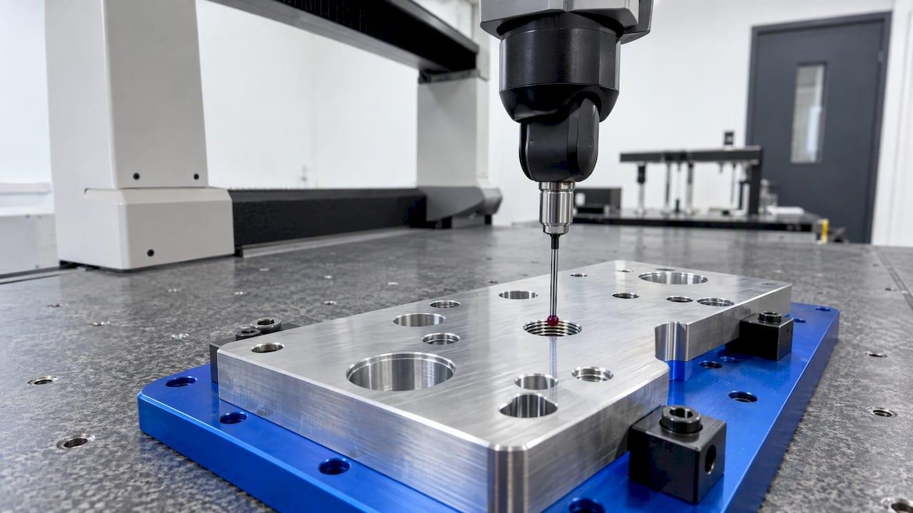
A projected tolerance zone moves the position tolerance of a hole out of the part and into the space where the mating part sits. It is shown by the Ⓟ symbol in the feature control frame, followed by a minimum height. It answers one question: where will the stud, screw or pin actually be once the parts are assembled, not where is the hole at the surface.
This guide explains the concept in plain terms, shows how to read and write the callout, walks through a worked example, and covers how inspectors verify it so that a tilted fastener does not slip through a pass/fail check.
TL;DR
- The projected tolerance zone (Ⓟ) extends a positional tolerance zone above the surface, so the axis is controlled where the mating part engages the fastener.
- It is used mainly for threaded holes and press-fit holes, where a tilted stud or pin could interfere with the clearance hole in the mating part.
- The projected height is a minimum, normally set by the maximum thickness of the mating part or the maximum height of the stud, not by thread depth.
- A drawing calls for a projected zone or a conventional zone on a feature, not both.
- Inspection checks the axis at the projected height, typically with a gage pin, or with CMM software that evaluates the extended axis.
Table of Contents
- What a projected tolerance zone is
- When to use the Ⓟ modifier
- How the symbol is written on a drawing
- How the projected zone relates to the position zone
- Setting the projected height
- Inspecting a projected tolerance zone
- Common mistakes
- Pre-inspection checklist
- Perspective
- Put projected zones into your inspection reports
- FAQ
- Sources
What a projected tolerance zone is
A conventional positional tolerance defines a cylindrical zone inside the part, running through the length of the hole. The hole axis must stay inside it. That is fine for a feature that mates inside its own thickness. It is not enough for a threaded hole that receives a stud sticking out of the surface.
The projected tolerance zone applies the tolerance to the feature's protrusion. According to Keyence's GD&T reference the zone can describe a virtual space for the mating part, which lets you build parts that are expected to fit as long as they are within their specifications. Put simply, the zone is a cylinder that starts at the surface and rises above it, and the axis of the hole must stay inside that cylinder for its full projected height.
The tec-ease explanation of projected tolerance states the engineering logic well: for threaded holes and holes that receive a pin, it is more important to know where the stud or fastener will be than where the hole is.
The problem it solves
Take a tapped hole. The thread is cut, the hole passes inspection at the surface, and the position is in tolerance. But the axis may be tilted inside the hole. Over a short distance inside the part, a small tilt moves the axis very little. Extend that same tilt 15 or 20 mm above the surface, where a stud stands, and the stud tip sits far from where the surface check suggested.
If the mating part has a clearance hole, that stud can bind against its wall. The part was "in tolerance" and still would not assemble. The projected zone closes that gap by moving the control to the height where the interference happens.
When to use the Ⓟ modifier
The modifier belongs on features where the fastener is fixed in one part and passes through another. The PTC documentation on optional modifiers describes the typical case: deviation in perpendicularity of threaded or press-fit holes could make screws, studs or similar fasteners interfere with mating parts. In a fixed fastener arrangement, the hole locates and orients the fastener, and interference occurs when the fastener leans within the location tolerance zone.
Good candidates:
- Tapped holes that receive studs, bolts or screws that pass through a mating plate.
- Press-fit dowel pin holes where the pin extends into a mating part.
- Any hole whose axis orientation, not just its surface location, decides whether the assembly goes together.
Poor candidates are floating fastener joints, where both parts have clearance holes and the bolt can shift to find its own position. There, the position tolerance of each part is the correct control, and a projected zone adds cost without adding function.
How the symbol is written on a drawing
The Ⓟ symbol is a capital P in a circle. According to GD&T Basics, it goes in the feature control frame after the tolerance value and any material condition modifiers, followed by the minimum projected height.
A typical frame reads as follows, from left to right:
- The position symbol.
- The diameter symbol and tolerance value, for example ⌀0.3.
- Any material condition modifier, if the design uses one.
- The Ⓟ symbol.
- The projected height, for example 10.
- The datum references in order of precedence.
The height can also be drawn instead of written in the frame. The tec-ease guide notes that the direction and height may be shown with a heavy chain line next to an extension of the hole centerline, and that when the direction is ambiguous, the side where the leader terminates can define the projection direction.
ASME and ISO differences
The two standards present the height differently. As the PTC GD&T advisor appendix explains, the ASME Y14.5M-1994 symbol is followed by a dimension value giving the minimum height of the zone, while the ISO standards dimension that minimum height at the geometric element itself. If your supplier chain spans both, confirm which standard the drawing invokes before you read the callout. This matters for teams working across the US, Canada, the UK, France and Germany, where drawings can arrive under either system.
How the projected zone relates to the position zone
Think of the projected zone as the position zone carried upward. The tolerance diameter is the same. What changes is where the axis is checked.
One point trips up many readers: this is not the same as simply tightening the position tolerance. As GD&T Seminars points out, the Ⓟ modifier targets the tilt that causes interference in fixed fastener assemblies while leaving useful room for lateral position drift. A tighter conventional tolerance would restrict both, and the shop would pay for precision the assembly does not need.

There is a practical consequence for manufacturing. A DESIGN TIPS paper on projected tolerance zones notes that the thread position tolerance can be larger when a projected zone is used, but perpendicularity must then be managed by working out the maximum angle that the tolerance size and length allow.
For a deeper look at how the base zone behaves, see our position tolerance guide for engineers and inspectors.
Setting the projected height
The height is the most commonly misjudged number in the callout. Three rules apply.
- It follows the mating part, not the hole. The value is usually the maximum thickness of the mating part or the maximum height of the pin or stud, according to the tec-ease guide.
- It is a minimum. The tec-ease guide also states that the specified value is a minimum, so an inspector may evaluate a taller projection, but never a shorter one.
- It is not the thread depth. Thread depth tells you how deep the hole goes. The projected height tells you how far above the surface the mating part reaches.
The DESIGN TIPS paper describes the same idea from the drawing side: the minimum height represents the maximum thickness or space above the threaded hole that the screwed-in part can occupy once assembled.
A worked example
This example is illustrative, not taken from a client drawing.
A machined housing has four tapped holes. A cover plate 10 mm thick bolts onto the housing with studs that pass through clearance holes in the plate. The designer writes the feature control frame as position, ⌀0.3, Ⓟ 10, datums A, B, C.
How to read it:
- The tolerance diameter is 0.3 mm.
- The zone starts at the housing surface and extends 10 mm above it, perpendicular to datum A.
- The extended axis of each tapped hole must stay inside a 0.3 mm diameter cylinder, 10 mm tall, located by the basic dimensions from the datums.
If the plate is 10 mm at its thickest, a stud that stays inside this zone for 10 mm of height will not hit the walls of a correctly sized clearance hole in the plate. A conventional zone could pass a hole whose axis leaves the zone above the surface. The projected zone cannot.
Inspecting a projected tolerance zone
Inspection has to check the axis at height, not at the surface. There are two common methods.
Gage pin method
The DESIGN TIPS paper describes the traditional approach: the inspector inserts the largest possible gage pin into the hole and measures the pin above the hole. The drawing tells the inspector how high up the pin to measure. The measured position of the pin at that height is then compared with the tolerance.

An exam-prep guide on projected zones describes a similar practice, using a threaded plug gage or pin that projects at the specified height so the whole projected axis can be confirmed inside the cylindrical zone.
CMM method
On a coordinate measuring machine, the programmer measures the hole, constructs its axis, and projects that axis to the specified height. The software then reports the position at that plane. Most CMM programs have a projected-zone option in the position evaluation, but the setting has to be switched on and given the correct height. A program that reports a surface position for a feature drawn with Ⓟ is quietly checking the wrong thing.
If you work with CMM output, check that the import maps each feature's callout, including the modifier and height, to the right result. Our CMM inspection software is built to import CMM data and map it to ballooned drawing characteristics, so the result lines up with the drawing requirement.
Common mistakes
- Checking at the surface. A hole can pass a conventional position check and still allow a tilted stud to bind against the mating part, which is the trap the exam-prep guide calls out.
- Using thread depth as the height. The height comes from the mating part.
- Writing both zones. The drawing specifies a projected zone or a conventional zone for the same feature, not both.
- Treating Ⓟ as a tighter tolerance. It targets tilt, as described above.
- Mixing standards. Reading an ISO drawing with ASME habits, or the reverse, leads to a wrong height or direction.
- Forgetting datum effects. A projected zone is still located from datums, so a poor datum setup moves the result. Our notes on datum shift cover how that shows up in inspection.
Pre-inspection checklist
Before a first article or routine inspection touches a projected feature, confirm:
- The feature control frame includes Ⓟ and a numeric height, or a chain line is drawn.
- The projection direction is clear.
- The drawing standard and revision are known.
- The datum reference frame matches the fixture and the CMM alignment.
- The inspection plan names the method, gage pin or CMM projection, and the height used.
- The report records the characteristic with its modifier, so a reviewer can see what was evaluated.
This last point is where documentation matters. Reviewers of first article packages need the result to be traceable to the drawing characteristic. Our guide to tolerance stack up shows how individual tolerances combine into assembly fit, which is the reason the projected height exists in the first place.
Perspective
In our work with quality teams, the projected zone is rarely misunderstood in theory. It goes wrong in the handoff: the drawing carries Ⓟ and a height, the inspection plan carries a surface position, and the report carries a single number nobody can trace back to either.
We believe the fix is structural. When each ballooned dimension keeps its full callout, including modifiers and heights, the person measuring sees the same requirement the designer wrote. When CMM results map to those same characteristics, a projected feature is evaluated as a projected feature.
That is how we designed QA-Report: ballooned drawings linked to measured results, out-of-tolerance flagging on each characteristic, and reports that your auditors can follow from drawing to result. For features like tapped holes that decide whether an assembly closes, we think that traceability is worth more than any shortcut.
Michael Chen
Put projected zones into your inspection reports
If your team documents first article and dimensional inspection, the callout should travel with the characteristic from the drawing to the report. QA-Report lets you balloon a PDF drawing, link each dimension to its measured value, flag out-of-tolerance results and produce a PDF report for review.

You can start on the Free plan at $0 per month, and paid plans run $49.99 per month for Basic and $149.99 per month for PRO. See the details on the QA-Report pricing page, or look at the platform features.
FAQ
What does the P in a circle mean in GD&T?
It is the projected tolerance zone symbol. It sits in the feature control frame after the tolerance value and any material condition modifiers, followed by a minimum height. It tells the inspector to evaluate the feature's axis at that height above the surface rather than only within the part.
Is a projected tolerance zone the same as a tighter position tolerance?
No. A tighter position tolerance restricts the hole in every direction. The projected zone specifically controls the tilt that makes a fixed fastener interfere with the mating part, while leaving more room for lateral position drift, as GD&T Seminars explains.
How do I choose the projected height?
Use the maximum thickness of the mating part or the maximum height of the stud or pin. The value is a minimum, and it is not the thread depth of the hole. If the mating part's thickness changes, the height on the drawing should be reviewed.
Can I use both a projected and a conventional zone on one feature?
The drawing specifies one or the other for a given feature. Choose the projected zone when the fastener is fixed in the part and passes through a mating part. Choose the conventional zone when the feature mates within its own length.
How is a projected zone inspected?
Commonly with a gage pin that is measured at the specified height above the surface, or with a CMM program that projects the constructed axis to that height. Either way, the inspection plan and the report should record the height used.
Sources
- GD&T Tips: Projected Tolerance (tec-ease)
- What Is a Projected Tolerance Zone? (Keyence)
- Optional Modifiers (PTC Creo Parametric)
- GD&T Advisor appendix (PTC Creo Elements/Direct)
- Projected Tolerance Zone (GD&T Basics)
- Projected Tolerance Zone: Equivalent to Tightening the Zone? (GD&T Seminars)
- Design Tips: Projected Tolerance Zone (PDF)
- Projected Tolerance Zones study guide