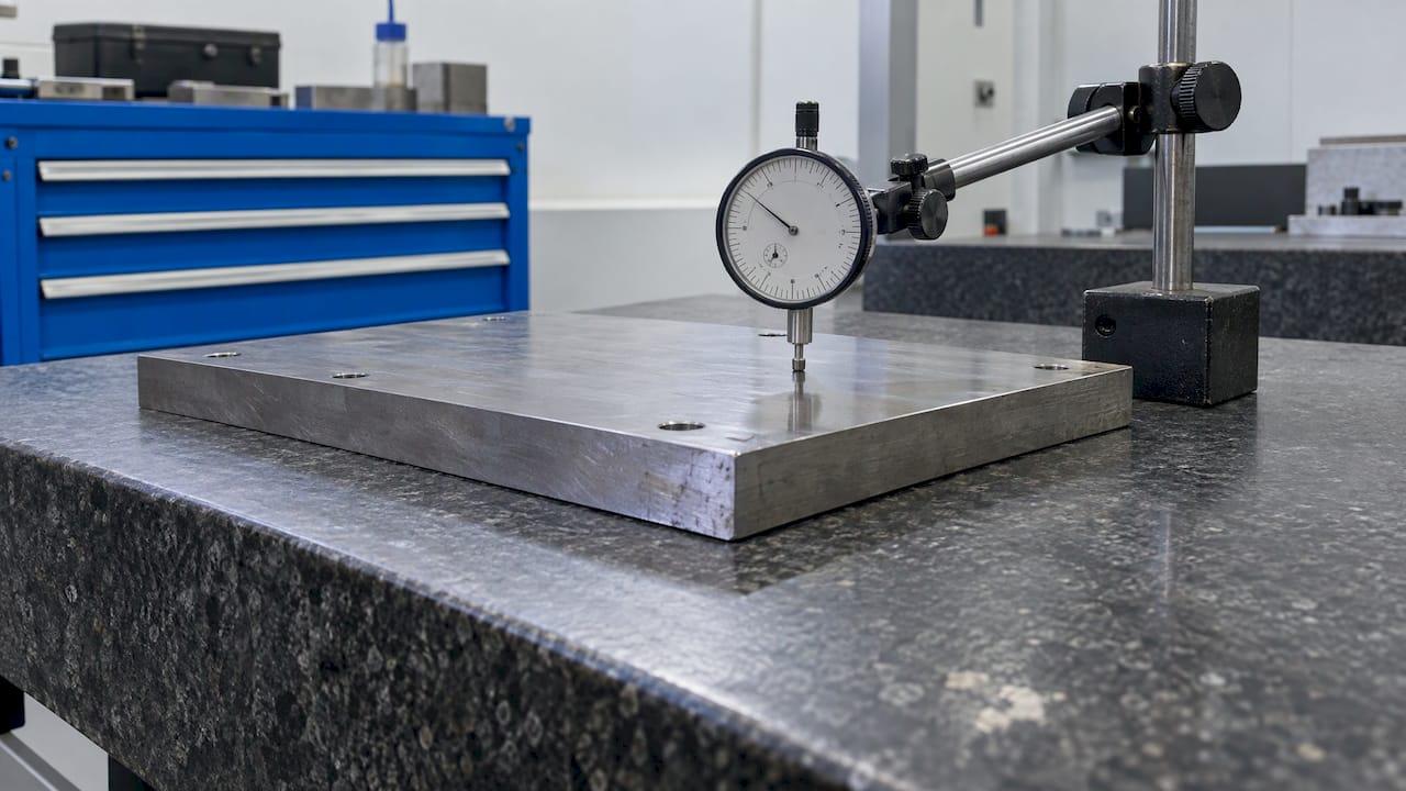
Flatness inspection answers one question: do all points on a surface fit between two parallel planes that are the tolerance value apart? You measure the surface with a probe or indicator (or a CMM), find the spread between the highest and lowest readings, and compare it to the drawing callout. The method you choose depends on part size, tolerance and what equipment you have. The way you set the part up and evaluate the data decides whether the result can be trusted.
This guide covers the definition, the main inspection methods, a step-by-step surface plate procedure, CMM evaluation, and the mistakes that lead to false accepts and false rejects.
TL;DR
- Flatness is a form tolerance with no datum reference. The zone is two parallel planes, and every point on the surface must lie between them.
- Sweeping a part that rests directly on a surface plate checks parallelism to the plate, not true flatness. Support the part on three adjustable points first.
- Use a measuring tool with resolution at least 10 times finer than the tolerance, and take enough points to represent the surface.
- Evaluate with minimum-zone logic. Least-squares can report a larger value than the minimum zone for the same points.
- Record the setup, point pattern and result in the inspection report so the check is traceable.
Table of Contents
- What flatness means on a drawing
- Flatness inspection methods and when each fits
- How to measure flatness on a surface plate
- Measuring flatness on a CMM
- Evaluating the result against the tolerance
- What affects flatness measurement accuracy
- Flatness versus straightness
- Perspective
- Keep flatness results audit-ready
- FAQ
- Sources
What flatness means on a drawing
Flatness is a form tolerance, and ASME's GD&T guide notes that a datum reference is not allowed with it. The surface is controlled only against itself. That is why flatness is a clean check of a datum surface before you use that surface to locate everything else.
The tolerance zone is the space between two parallel planes. A callout of 0.004 in means the highest and lowest points of the surface must fit between planes 0.004 in apart. The planes can tilt in any direction to enclose the surface. Only the separation matters.
For measured data, an academic study of flatness evaluation explains that ANSI Y14.5 evaluates form tolerances against an ideal geometric feature. ISO recommends minimum-zone evaluation: the least possible normal distance between two parallel planes enclosing all measured points. Mitutoyo's technical bulletin makes the same point in shop terms: in practice, you read the range between the highest and lowest measured values.
Flatness inspection methods and when each fits
There is no single best method. Match the method to the part and the tolerance.
| Method | Best for | What you read | Main limitation |
|---|---|---|---|
| Surface plate, three supports and dial indicator or height gauge | Small to mid-size machined parts, general shop use | Total indicator spread across the surface | Coverage depends on the sweep pattern |
| Probe set into a surface plate | Small flush parts, repeat checks | Variation on an amplifier readout as the part moves over the probe | Part size is limited by the plate and probe |
| CMM point sampling | Parts with a model or drawing, reports that need data | Minimum-zone flatness from sampled points | Accuracy depends on number and spread of points |
| Optical flat with monochromatic light | Very flat, small, polished surfaces | Interference bands showing height differences | Needs clean, reflective surfaces and a controlled environment |
| Interferometer (Fizeau, Twyman–Green) | Optical flats and precision reference surfaces | Surface form at nanometer level | Sensitive to alignment, temperature and gravity |
| Autocollimator, electronic levels, laser | Calibrating large plates and machine surfaces | Overall flatness across a large area | Specialist setup and calibration skill |
Surface plate methods
Mahr Federal's metrology guide describes a surface plate as a broad, smooth, stable reference used with height gauges, indicators, gage blocks, angle plates and squares. For small parts, Modern Machine Shop describes a hole bored in the plate with an embedded gage head or air jet. The part is moved over the probe and the variation is read on the amplifier, with no height stand needed.
The same Mahr guide explains the logic: the three highest support points establish the riding plane, and the probe senses variation. It also cautions that a single probe cannot explore every square millimeter, so you follow a coverage pattern and assume the unmeasured areas are represented by it.
Optical and interferometric methods
For direct optical inspection, Kemet describes an optical flat illuminated by monochromatic sodium light. Bright and dark bands reveal height differences between the test surface and the reference plane. For optical components, University of Arizona course material identifies Fizeau and Twyman–Green interferometers. Twyman–Green is more versatile but needs more high-quality optical components. Most machine shops never need these, but they explain how reference surfaces are verified.

Methods for the plate itself
The surface plate is your reference, so it needs its own checks. Mitutoyo's bulletin separates overall flatness across the whole plate from local variation, or repeat reading, over a small area. Both need calibration. For overall flatness it lists a laser interferometer, autocollimator, electronic levels, or a master straightedge with an indicator. For local variation, it points to a repeat-reading gage.
Starrett reports that ASME B89.3.7 covers overall granite plate flatness using diagonals, perimeter and center lines with a calibrated straightedge, adjustable supports and an indicator. A national laboratory report on surface plate calibration describes a line-based process that permits a closure error of 0.0001 inch (2.5 micrometers).
How to measure flatness on a surface plate
This is the most common shop method. The goal is to isolate flatness from tilt and parallelism error.
- Clean the plate, the part and any gage blocks. Let everything reach the same temperature as the inspection area.
- Check that the plate itself is in calibration and that the area you will use is not worn.
- Support the part on three adjustable jacks or equal gage-block stacks. Place them under the surface you are measuring, as widely spaced as the part allows.
- Zero the indicator on a reference at about the part height, or simply zero it on the surface at one of the support points.
- Adjust the jacks until the indicator reads the same at all three support locations. This levels the part's own surface and removes tilt from the reading.
- Sweep the whole surface with the indicator or move the part across a fixed probe. Follow a defined pattern: perimeter, diagonals and a grid across the middle.
- Record the highest and lowest readings. The total spread approximates the flatness error.
- Compare that value to the drawing tolerance and note the pattern and instrument in the report.
The step that people skip is the three-point leveling. A calibration lab's guide points out that placing a part directly on the plate and sweeping the top face with a height gauge measures parallelism to the table. True flatness needs the adjustment method to separate the two. The same guide also stresses checking datum surfaces for flatness, because a non-flat datum corrupts every downstream measurement on the part.
A canted surface is a setup problem, not a defect
A common shop question: you sweep the indicator and see a steady slope across the surface. If the bottom face is not parallel to the top, the part rests tilted and the reading includes that wedge. Leveling on three supports, as in step 5, removes it. What remains is the form error the drawing controls.
Measuring flatness on a CMM
A CMM touches a set of points on the surface and software fits two parallel planes around them. KEYENCE America notes that ordinary CMM flatness measurement requires contacting multiple points, and that more points can improve accuracy on large areas at the cost of extra measurement effort.
There is evidence behind that trade-off. A metrology journal paper defines flatness for CMM work as the minimum distance between two parallel planes containing all sampled points, and notes that software may use least-squares or minimax criteria. It reports that more points represent the surface better, tend to raise the estimated flatness toward a convergent value, and reduce uncertainty. Sparse sampling can therefore lead to a wrong conformity decision.
Practical CMM guidance:
- Spread points across the surface, including edges and corners, not just a tight cluster.
- Increase point count as the surface area grows or the tolerance tightens.
- Review the point cloud for a single bad touch, such as debris or a probe skip. Minimum-zone results can swing on one outlier, so apply your software's filtering rules and document them.
- Keep the part temperature and fixturing stable, and avoid clamping that bends a thin part.
If your team imports CMM output into inspection reports, our CMM inspection software page shows how measured values map back to drawing dimensions.
Evaluating the result against the tolerance
Compare the measured flatness, the minimum distance between two parallel planes that enclose all points, to the drawing callout. If the value exceeds the tolerance, the part fails.
The evaluation method matters. According to the same calibration lab guide, minimum-zone (the smallest sandwich) is the recognized criterion under ASME Y14.5 and ISO 1101, and least-squares can report a value above the limit when the minimum zone would pass the same points. The reason is geometric: the peak-to-valley range normal to a least-squares plane cannot be smaller than the minimum-zone range. If your software offers a choice, pick minimum zone for acceptance decisions and state it in the report.
A hand surface-plate reading is different. The indicator spread after leveling approximates the minimum zone, which is why the leveling step matters.
What affects flatness measurement accuracy
Instrument resolution
A widely used rule is the 10:1 ratio. The measuring tool should resolve at least 10 times finer than the tolerance. The calibration lab guide gives the example that a 0.05 mm tolerance needs a tool resolving to at least 0.005 mm. A dial indicator reading in 0.001 in steps cannot judge a 0.002 in callout with confidence.
Sampling pattern
Fewer points mean more chance of missing the high or low spot. Define the pattern in your inspection plan and use the same one each time, so results compare from part to part and shift to shift.
Temperature and setup
Heat from hands, lights or a recent machine cycle distorts parts and plates. In precision optical work, a Fizeau uncertainty study names off-center alignment, temperature instability and gravity deformation as major contributors. In its 300 mm experiment it observed up to 99 nm difference from orientation-related gravity effects. Shop parts have far looser tolerances, but the lesson carries over: setup and environment can matter more than instrument resolution.
Datum and reference surface condition
A worn plate or a burr under the part gives readings that are not about the part. Check the reference before the part. For more on how datum choice drives false rejects, see our guide to datum selection in inspection. To quantify how all of these add up, the measurement uncertainty workflow walks through the steps.
Flatness versus straightness
Both are form tolerances, and both are measured against two parallel boundaries, but they control different things. Flatness controls a whole surface with a zone of two parallel planes. Straightness, applied to a surface, controls individual line elements, each of which must lie between two parallel lines in the view. A surface can have every line element straight within the tolerance and still fail flatness across the surface, so flatness is the broader check.

In practice, you measure straightness by sweeping along a line and flatness by covering the area. When a drawing controls an entire surface shape relative to a basic profile instead of just form, a profile tolerance applies. Our guides to profile tolerance inspection and surface profile tolerance cover that case.
Perspective
In our experience, flatness checks rarely fail because the gauge is bad. They fail because the setup was not recorded. Which points were taken, how the part was supported, which evaluation was used: these details decide whether the result is reproducible.
That is why we design QA-Report around the link between the ballooned drawing characteristic and its measured result. A flatness value that sits next to its callout, with out-of-tolerance flags and a report your auditor can follow, is easier to defend than a number on a scrap of paper.
Teams in aerospace, automotive and medical production also need that record to survive across shifts, suppliers and revisions. We built the platform so inspectors on the floor, quality engineers and customers work from the same data, whether the readings come from a surface plate or a CMM.
Michael Chen
Keep flatness results audit-ready
QA-Report is a cloud-based platform where you balloon the drawing, link each characteristic to its measured result, flag out-of-tolerance values and produce a PDF report. You can import CMM data or enter surface plate readings by hand, so flatness sits in the same report as your other dimensions.
You can start on the Free plan at $0 per month. Basic is $49.99 per month and PRO is $149.99 per month. On-Premise and Enterprise Solutions are available without a published price. Details are on the pricing page.

If you are deciding how many parts to check, our guide to attribute versus variable sampling explains when a measured value is worth recording.
FAQ
How do you verify flatness?
Support the part on three adjustable points, level the surface so the indicator reads the same at all three, then sweep the whole surface in a set pattern. The spread between the highest and lowest readings approximates flatness. Compare it to the drawing tolerance.
What is flatness in GD&T?
Flatness is a form tolerance that controls how much a surface may vary from a perfect plane. The zone is two parallel planes, and the whole surface must lie between them. It takes no datum reference.
Can I measure flatness with a height gauge?
Yes, but only with the right setup. If the part rests directly on the plate, you measure parallelism to the plate. Level the surface on three adjustable supports first, then sweep, so tilt does not count as flatness error.
Why does my CMM flatness differ from my surface plate result?
The two methods sample different points and may evaluate differently. A CMM uses a limited set of touches and a fitting criterion, while a surface plate sweep covers a pattern. Use minimum-zone evaluation, take more points on larger surfaces and check for outliers.
Sources
- ASME GD&T topical guide
- Flatness tolerance evaluation: an approximate minimum zone approach
- Surface Plates: Accuracy and Calibration (Mitutoyo)
- Flatness Measurements (Mahr Federal)
- Measuring for Flatness, Thickness and Parallelism (Modern Machine Shop)
- Measuring Flatness: Techniques and Methods (Kemet)
- Testing Flat Surface Optical Components (University of Arizona)
- Precision Granite Inspection Products (Starrett)
- Comparison of Calibration Methods for a Surface Plate (OSTI)
- How to measure flatness of a surface (Sarkinen Calibrating)
- KEYENCE flatness measurement application
- Comparison of the GUM and Monte Carlo methods on flatness
- Uncertainty evaluation for absolute flatness measurement