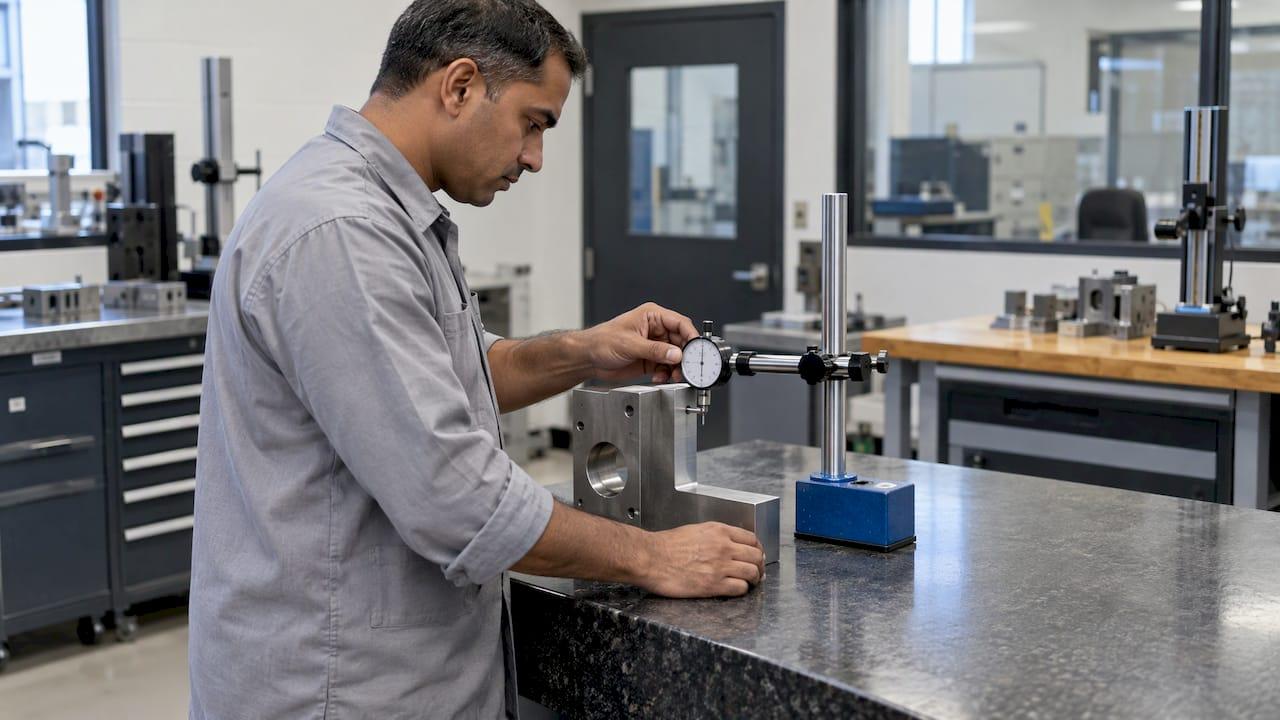
Perpendicularity inspection answers one question: does a surface, axis or center plane stay inside a tolerance zone that sits at exactly 90° to a datum? You answer it by establishing the datum first, collecting enough points on the controlled feature, fitting the correct zone (two parallel planes or a cylinder), and comparing the result with the value in the feature control frame. A square and indicator on a surface plate handle simple parts. A CMM handles axes, holes and complex geometry. Either way, the result only helps your team if it is tied to the right drawing dimension and recorded in the report.
This guide is for quality engineers and inspectors in US shops who need a repeatable routine, from reading the callout to documenting the result.
TL;DR
- Perpendicularity is a linear tolerance zone (a width or a diameter), not an angle. A tolerance of 0.2 means a zone 0.2 wide, not 0.2 degrees.
- The zone shape depends on what is controlled: two parallel planes for a surface or center plane, a cylinder for an axis.
- Establish the datum before you judge the feature. The zone is perpendicular to the perfect datum, not to the part's imperfect surface.
- Use comparator setups for simple surfaces and a CMM for axes, holes and complex parts.
- Report the measured value, the zone, the datum and the pass or fail result against the balloon on the drawing.
Table of Contents
- What the perpendicularity callout controls
- Surface, axis and center plane: three zones, three inspections
- Datums first: the step most false rejects come from
- How to measure perpendicularity
- Worked example: surface and axis
- Evaluating and reporting the result
- Common errors to avoid
- Keeping measurement and drawing linked
- Our view on perpendicularity inspection
- FAQ
- Sources
What the perpendicularity callout controls
Perpendicularity is an orientation control. ASME Y14.5 is the US standard for dimensioning and tolerancing, and the 2018 edition (reaffirmed 2024) remains in effect. Under it, a feature must lie within a zone that is perpendicular to a datum plane or axis. The datum reference is required, so a perpendicularity callout without one is incomplete.
Three points trip up newer inspectors.
The value is a distance, not an angle. Reata Engineering notes that perpendicularity is measured in length, and that a request for "perpendicularity of .5 degrees" is really an angle callout of 90° ± 0.5°. The two are not the same: an angle tolerance is two-dimensional, while perpendicularity is three-dimensional and also limits form variation.
Perfect 90° does not exist on a real part. Tool speed, pressure and wear all introduce small angle variations, so the callout sets the range that still lets the part function.
It does not control location. The tolerance zone can float to fit the feature. Perpendicularity restricts tilt, and Redlux points out that the parallel planes may be freely translated, so position needs its own control if it matters.
If the frame itself is unclear, our guide to what a feature control frame tells you walks through each compartment.

Surface, axis and center plane: three zones, three inspections
The same symbol produces different inspection work depending on what it points at.
| Controlled feature | Tolerance zone | What you check |
|---|---|---|
| Flat surface | Two parallel planes, a set distance apart, perpendicular to the datum | The whole surface lies between the planes |
| Axis of a hole or pin | Cylinder with the stated diameter, perpendicular to the datum | The derived axis stays inside the cylinder |
| Center plane of a slot or width | Two parallel planes centered on the datum-perpendicular direction | The mid-plane points lie inside the band |
Surface perpendicularity
For a surface, the zone is two parallel planes perpendicular to the datum plane, and the entire surface must lie between them, as CMM Compass describes. That has a useful side effect. Drafter Inc explains that a surface perpendicularity control also limits flatness to the same value: a 0.010 perpendicularity means the surface is flat to at least 0.010. If you also inspect a separate flatness callout, see our flatness inspection guide.
Axis perpendicularity
For an axis, the zone is a cylinder whose diameter equals the value in the frame, standing perpendicular to the datum. The feature's derived axis must stay inside it. Axis perpendicularity is often used with a material condition modifier, but not always, according to Machining Doctor. Modifiers are allowed only when the controlled feature is a feature of size, such as a hole or pin.
Center plane perpendicularity
When the control applies to a width, it governs the mid-plane between the two faces. Redlux notes that neither face has to be at 90° to the datum, as long as the mid-plane points at every cross section fall inside the band. Inspectors who check each face separately can reject parts that actually conform.
Material conditions
When the controlled feature is a feature of size, MMC or LMC can apply. Drafter Inc describes the effect: the stated tolerance applies at that condition, and the zone grows as the feature's size departs from it. An illustrative example: a hole with a 0.1 perpendicularity tolerance at MMC, measured 0.2 larger than its smallest limit, can lean within a 0.3 diameter zone. Our article on MMC vs LMC covers how to choose and verify these conditions.
Datums first: the step most false rejects come from
The tolerance zone is perpendicular to the perfect datum, not to the real, imperfect surface of the part. Dimensional Consulting makes this point in its gage-based explanation, and it is why inspectors must establish datums before judging the controlled feature. Datum selection decides what you evaluate.
On a surface plate, the datum feature rests on the plate, which acts as the datum simulator. On a CMM, you probe the datum feature and construct the datum plane or axis from the points. In both cases, the way the part is held must match the drawing's datum order. When fixtures and drawings disagree, good parts fail. Two of our articles go deeper: GD&T datums for inspection teams and the hidden cost of misaligned datums. If the datum is a feature of size, also review datum shift.
How to measure perpendicularity
The NIST guide to GD&T for digital manufacturing separates specification from measurement. Simple instruments suit squareness and flatness checks, and CMMs suit complex surfaces, complex tasks and high automation. Its manual toolkit includes calipers, micrometers, gauge pins and dial or test indicators.
Method 1: Comparator setup on a surface plate
This suits a flat surface on a part that can sit on its datum face.
- Clean the part and plate. Burrs and chips under the datum face tilt the whole setup.
- Seat the datum feature on the surface plate.
- Support the part against an angle plate or square if it cannot stand stably alone.
- Zero a dial indicator on the controlled surface at one point.
- Sweep the indicator across the entire surface.
- Read the total indicator reading (TIR). NIST describes inspecting the entire surface and reading TIR as the perpendicularity value.
The weak point is that the indicator travel must be perpendicular to the plate. Check the stand and the square before trusting the number.
Method 2: CMM inspection
A CMM suits axes, holes, centerplanes and parts that do not rest naturally on a datum. The sequence is:
- Probe the datum feature with enough points to define it, and construct the datum plane or axis.
- Probe the controlled feature. A surface needs points spread across the whole area. A hole needs points at several depths, so the axis direction is real.
- Derive the axis or center plane from the measured points.
- Evaluate it against the zone: two planes for a surface, a cylinder for an axis.
- Compare the result with the frame value, adjusted for any material condition bonus.
The academic text Design for Fit by Far Etesami explains why this works: CMM soft gaging samples a surface at many points and simulates a theoretical gaging process, which comes closest to inspecting features according to theoretical gages. For axis perpendicularity, the datum feature goes against the datum simulator and the axis is checked for containment within the zone. For background on the machine itself, read our simple guide to CMM inspection.
Which method to choose
Makerstage lists a square plus indicator, or a CMM with a datum plane established, as the usual methods. It gives typical CNC ranges of 0.002 to 0.005 in. for easy tolerances and 0.0005 to 0.001 in. for tight ones. Tight tolerances are where measurement uncertainty starts to matter, so a CMM with a defined datum is the safer route there.
Worked example: surface and axis
These numbers are illustrative.
Surface. The drawing calls a perpendicularity of 0.2 to datum A on a side face. The zone is two planes 0.2 apart, perpendicular to A. You rest the part on datum A and sweep an indicator over the whole face. The TIR is 0.14. The entire surface fits within a 0.2 zone, so the part passes. Had the face been tilted but flat, the TIR would still show the tilt, because the zone is fixed to the datum.
Axis. A post is called out at 0.2 diameter perpendicularity to datum A, at RFS. On the CMM you construct datum A, probe the post at three heights and derive its axis. The axis sits at most 0.07 off the perpendicular line through the zone center. A cylinder of 0.14 diameter contains it, which is below 0.2, so it passes.

Evaluating and reporting the result
A measured number alone is not a record. A report that survives an audit shows:
- the drawing balloon or characteristic number
- the feature type (surface, axis, center plane) and zone shape
- the datum and how it was established
- the stated tolerance, plus any MMC or LMC bonus
- the measured value, the pass or fail result and the instrument used
- the ASME or ISO edition named on the drawing
The edition matters. KingsForm's GD&T guide states that ASME and ISO defaults are not fully interchangeable, so the governing standard must appear on the drawing. It also advises verifying the tolerance zone, not just convenient points, since point checks are a high-risk error when the tolerance is a continuous surface zone.
If the drawing relies on an indirect control such as position, runout or profile, remember that these can limit perpendicularity but are not inspected as perpendicularity. The Inspection Technologies reference says that if perpendicularity must be inspected, it should be specified directly, with a tolerance smaller than any indirect control's. For profile-based callouts, see our surface profile tolerance guide and profile tolerance inspection.
Common errors to avoid
- Treating the value as degrees. Convert your thinking to a zone width.
- Inspecting faces when the callout is a center plane. Evaluate the mid-plane.
- Skipping the datum. Measuring to the machine table or a convenient edge changes the answer.
- Too few points. A surface zone is continuous, and a handful of points can miss a bow or tilt.
- Ignoring the material condition. A missing bonus tolerance causes false rejects, and an unearned one causes escapes.
- Mixing standards. Check the edition on the drawing before you interpret the frame.
Keeping measurement and drawing linked
Most perpendicularity problems on the floor are bookkeeping problems: the result sits in a CMM printout, the drawing is a different file, and the report is typed by hand. QA-Report is a cloud-based inspection platform that imports CMM data and maps results to ballooned drawing dimensions. It flags out-of-tolerance deviations automatically and produces PDF reports for FAI, AS9102 and PPAP requirements.
Plans are published on the pricing page: Free at $0 per month, Basic at $49.99 per month and PRO at $149.99 per month. On-Premise and Enterprise Solutions are priced on request. To see how the CMM workflow works, visit the CMM inspection software page.

If your team inspects perpendicularity on every first article, start with one part: balloon the drawing, import the CMM results and let the platform compare each characteristic with its tolerance.
Our view on perpendicularity inspection
Perpendicularity is rarely hard to measure. It is hard to document consistently. The geometry is settled by the standard, yet two inspectors can reach different answers because one set up the datum differently or counted fewer points.
We built QA-Report around the idea that the drawing is the source of truth. When every dimension is ballooned and every measured result is linked to its balloon, nobody has to wonder which tolerance a number belongs to. Out-of-tolerance deviations are flagged as the data arrives, not days later during report assembly.
For teams working to AS9100 or PPAP, we think this traceability matters as much as the measurement. A broken chain between drawing, measurement and report is where audit findings start. Keeping that chain in one place, with CMM import, role-based access and shareable reports, is what we offer.
Michael Chen
FAQ
What can be used to check for perpendicularity?
For simple flat features, use a surface plate with an angle plate or square and a dial indicator, reading TIR across the surface. For axes, holes and complex parts, a CMM is the better tool. NIST lists calipers, micrometers, gauge pins and indicators among manual instruments.
Does perpendicular mean exactly 90 degrees?
The nominal relationship is 90°, but the tolerance is a zone with a width, not an angle. Real parts never hold exactly 90.000°, so the callout sets how much the surface, axis or center plane may vary while the part still works.
What is the symbol for perpendicularity?
The symbol is ⟂, two lines meeting at a right angle. It always appears in a feature control frame with a tolerance value and at least one datum reference.
How is perpendicularity different from angularity?
Perpendicularity is a special case of angularity fixed at 90°. Angularity can control any basic angle, while parallelism and perpendicularity are set at 0° or 180° and 90°. Both are orientation controls, so the zone is fixed relative to the datum, not located in space.
Sources
- ASME Y14.5 Dimensioning and Tolerancing
- 4 Facts to Know About Perpendicularity, Reata Engineering
- Practical GD&T: Perpendicularity Measurement, Redlux
- Measurement of Perpendicularity with CMM, CMM Compass
- Perpendicularity, Drafter Inc
- Perpendicularity in GD&T, Machining Doctor
- Perpendicularity, Dimensional Consulting
- Geometric Dimensioning and Tolerancing for Digital Manufacturing, NIST
- Design for Fit, Far Etesami
- Flatness vs Parallelism vs Perpendicularity, Makerstage
- GD&T Quick Guide, KingsForm
- Orientation Controls, Inspection Technologies