Concentricity tolerance limits how far the median points of a round feature can drift from a datum axis. The zone is a cylinder centered on that datum, and every median point along the feature must sit inside it. The control is also one of the most misread symbols in GD&T. Current ASME practice has removed it, yet it still turns up on legacy drawings and on ISO-based prints, so inspectors still have to read it, check it and decide what to do when it shows up.
This guide covers the definition, the feature control frame, the status of the symbol in the standards, the difference between concentricity, runout, position and cylindricity, and a practical way to inspect it.
TL;DR
- Concentricity controls derived median points of a feature of revolution against a datum axis. It does not control the surface directly.
- It is a regardless-of-feature-size control. Material condition modifiers are not allowed.
- ASME Y14.5-2018 removed concentricity. Position, runout or total runout are the recommended replacements, but the symbol still appears on older drawings and in ISO 1101.
- Checking it properly means collecting median points at many cross-sections, which is CMM work. A dial indicator reading is runout, not concentricity.
- Before you accept or reject a part, confirm which standard and revision the drawing follows.
Table of Contents
- What concentricity tolerance controls
- How concentricity appears on a drawing
- Is concentricity still in ASME Y14.5?
- Concentricity vs runout, position and cylindricity
- How to check concentricity
- Our perspective
- Keep concentricity results traceable
- FAQ
- Sources
What concentricity tolerance controls
Concentricity describes a condition in which the median points of diametrically opposed elements of a feature of revolution are congruent with the axis of a datum feature. PTC's GD&T reference puts it that way. A median point is simply the midpoint of a line joining two opposite points on one cross-section of the feature. Machining Doctor's reference explains it the same way. To comply, the median point of every relevant cross-section along the feature must stay inside the tolerance zone.
Three consequences follow:
- It is a three-dimensional control. One shop reference describes it as ensuring that the central derived median points of a cylindrical feature align with a datum axis.
- It says nothing directly about the outer surface. A bent or lobed shaft can have median points that sit perfectly on the axis, so the surface can look poor while concentricity passes.
- It needs a datum. A concentricity tolerance without a datum reference has nothing to be concentric to.
The tolerance zone
The zone is a cylinder whose axis coincides with the datum axis. The diameter of that cylinder is the tolerance value in the feature control frame. All the median points of the controlled feature, taken across its length, must fall inside it.
A worked example makes it concrete. Take a bore with a concentricity tolerance of 0.010 in. to datum A. The zone is a cylinder 0.010 in. in diameter around the datum A axis. Any median point may sit up to 0.005 in. from the datum axis in any radial direction, because the zone is a diameter and the offset is a radius. If the bore's median points wander in a spiral inside that cylinder, the part passes. If a single cross-section's median point lands outside, it fails, even when the bore is round and well within its size limits.
The practical reading used on many shop floors is the same idea expressed with an indicator. The Precision Machined Products Association describes it as a shared axis lying within a cylinder whose diameter equals the tolerance, and notes that conventional indicator checks express the requirement as full indicator movement when the part is rotated on the datum axis. That is a convenient shop proxy, and it has limits, covered below.

How concentricity appears on a drawing
The feature control frame is read left to right. One guide lists three blocks: the geometric characteristic symbol (two concentric circles), the feature tolerance, and the datum reference. For a refresher on reading every compartment of a frame, see our guide to what a feature control frame tells you.
A typical frame reads: concentricity symbol, then 0.010, then A. That means the median points of the controlled feature must lie within a 0.010 diameter cylinder coaxial with datum axis A.
No material condition modifiers
The NORAMARK ASME Y14.5 chart lists concentricity as datum-referenced and RFS-only, with no MMC or LMC modifier allowed. Runsom's guide gives the reason: material modifiers would add bonus tolerance and enlarge the zone, and that contradicts what the control is for. So a frame showing a circled M or L after the tolerance is not a valid concentricity callout. Flag it to engineering instead of guessing.
Datums matter more than the symbol
Because the zone is anchored to a datum axis, the way you establish that axis changes the result. A datum feature held in a V-block, a chuck or a mandrel can each give a slightly different axis. If your fixturing does not match the datum definition on the drawing, you will see false rejects or false accepts. Our articles on GD&T datums for inspection teams and the datum reference frame walk through that setup, and why GD&T doesn't match your fixtures covers the cost when it goes wrong.
Is concentricity still in ASME Y14.5?
No, not in the current edition. GD&T Basics reports that concentricity was eliminated from ASME Y14.5 in the 2018 edition, citing measurement complexity and limited practicality, and recommends position, runout or total runout instead. Mitutoyo's summary of the 2018 changes says that the terms, symbols and concepts for both concentricity and symmetry were removed, and that position and runout are better options for controlling the location of coaxial features. A NIST publication on digital GD&T makes the same point: the concentricity definition was complex and often misunderstood, so position should control a feature's axis and runout its surface.
That does not make the symbol disappear from your inbox. Redlux notes that concentricity remains valid in ISO 1101 and can appear on legacy drawings made under earlier ASME revisions. So you will meet it in three places:
- Older prints created to ASME Y14.5-2009 or earlier, still in production.
- Drawings from customers or suppliers working to ISO.
- Drawings that mix conventions, which happens more than anyone admits.
ASME and ISO use the word differently
Mitutoyo's notes draw a distinction worth remembering. ASME concentricity works with opposing median points. In ISO terminology, concentricity controls a two-dimensional center point, while coaxiality controls a three-dimensional derived median line. Same word family, different meaning. Before you inspect, confirm which standard and revision the drawing cites in its title block or general notes.
Concentricity vs runout, position and cylindricity
This is where most confusion happens, and it drives the most common questions about the symbol. The short version: concentricity controls median points, runout measures surface variation as the part rotates, and position can control a feature's axis (source). The table puts the four side by side.
| Control | What it governs | Datum required | Typical inspection |
|---|---|---|---|
| Concentricity | Derived median points vs a datum axis | Yes | CMM with many cross-sections |
| Circular runout | Surface variation at each cross-section during rotation | Yes | Indicator on a rotating part |
| Total runout | Surface variation along the whole surface during rotation | Yes | Indicator traversed along the surface |
| Position (axis) | Location of the feature's axis relative to datums | Yes | CMM or functional gauge |
| Cylindricity | Form of the cylinder: roundness, straightness, taper | No | Form measurement or CMM |
Concentricity vs runout
Runout combines location and form in one reading. If a shaft is slightly oval and slightly off-axis, the indicator sees both. Concentricity ignores the form and looks only at where the median points are. That means a part can fail runout and still pass concentricity, but the reverse is rarely true when the form error is small. Because the indicator reading adds the form error to twice the radial offset of the axis, runout is usually the tighter, more conservative check. Our guide to circular vs total runout explains how to pick between the two runout types.

Concentricity vs position
Position applied to an axis with a diametral zone does the same location job and allows a material condition modifier when the function justifies bonus tolerance. It is also easier to inspect with a functional gauge or a standard CMM routine. Our position tolerance guide covers how the zones and modifiers work.
Concentricity vs cylindricity
Cylindricity controls the overall shape of a cylindrical feature, including roundness and straightness, and does not need a datum. Concentricity controls where the median points sit relative to a datum axis. One is about form, the other about location. A perfectly cylindrical bore can be badly off-axis, and a well-centered bore can be out of round.
When a drawing should use something else
If you are the designer or an engineer reviewing a legacy print, the usual substitution logic is:
- If the function is a rotating fit, balance or sealing surface, use circular or total runout on the surface.
- If the function is the location of an axis, use position with a datum axis.
- If you want a pure median-point idea, ask whether the function really depends on it. Often it does not.
If the drawing does say concentricity and you are inspecting to it, inspect to it as written. Changing the callout is an engineering decision, not an inspector's call.
How to check concentricity
Checking concentricity requires measuring median points across multiple cross-sections and comparing the resulting axis with the datum axis. A CMM is a reliable way to do it (source). The steps below describe a typical CMM routine.
- Establish the datum axis. Measure the datum feature according to the drawing, with enough points and enough length to define the axis stably.
- Choose cross-sections. Pick planes along the controlled feature. More planes give a more truthful picture. Two or three on a long feature will miss a bow.
- Measure each section. Collect points around the circle in each plane and compute the center. For a rigorous median point, use diametrically opposed pairs.
- Compute offsets. For each section, find the distance from its median point to the datum axis.
- Compare against the zone. The diameter of the smallest cylinder around the datum axis that contains all median points is the concentricity value. It must not exceed the tolerance.
- Record the evidence. Keep the datum setup, number of sections and raw points with the result, so the decision can be audited.
Keyence describes a simpler CMM method for a single plane: measure points on the datum circle and on the target circle, and derive the concentricity result from their centers. That works when the feature is short and the drawing allows a plane-based check.
Indicator checks and their limits
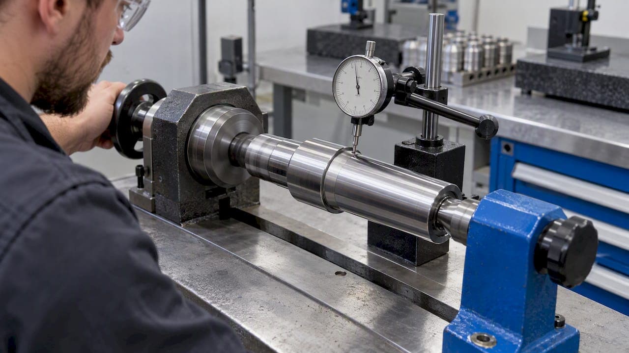
The shop-floor alternative is to rotate the part on the datum axis and watch full indicator movement on the target diameters. PMPA's designer guide describes this and notes that the tolerance should allow for roundness, runout and perpendicularity. That is the catch: an indicator reads surface, so it reports runout. Treating the reading as concentricity can reject good parts, because form error is counted as location error. If you use it, say so in the inspection record and agree the method with the customer.
Common mistakes
- Calling a dial indicator result concentricity.
- Measuring a single section and reporting it for the whole feature.
- Using a different datum setup than the drawing defines.
- Applying an MMC modifier that the control does not allow.
- Ignoring the standard revision, then arguing about a symbol that means different things in ASME and ISO.
Our perspective
We see concentricity tolerance most often when a team inherits an old drawing and a new inspection system at the same time. The callout is valid, but the work needed to prove it is heavy: many cross-sections, a clean datum setup, and a record that shows how the decision was made. When that record lives in spreadsheets and scattered CMM exports, the point of the median-point idea gets lost, and so does the traceability.
Our advice is simple. Read the standard and revision on the drawing first. Inspect what is written, with the method that matches the definition. Where the function allows, raise a request to move the callout to position or runout, which the current ASME standard prefers and which are easier to verify consistently. And whatever you decide, keep the datum setup, the measured values and the pass or fail decision linked to the balloon on the drawing, so the next person can see exactly what was done.
— Michael Chen
Keep concentricity results traceable
When a drawing carries a concentricity, runout or position callout, the inspection only helps if each measured value stays tied to its balloon, its datum and its tolerance. QA-Report links ballooned drawing dimensions to measured results, imports CMM data, flags out-of-tolerance values automatically and produces PDF reports for FAI, AS9102 and PPAP submissions. You can start on the Free plan, and the Basic plan is $49.99 per month and PRO is $149.99 per month. See the plans and pricing to pick the one that fits your team.

If you want to see how GD&T callouts are pulled from a drawing and linked to evidence, read about automated GD&T extraction, or try the platform from the QA-Report home page.
FAQ
How do you calculate concentricity of two circles?
Find the center of each circle from measured points, then measure the distance between the two centers. For a datum circle and a target circle in one plane, the concentricity value is twice that distance, because the tolerance is a diameter and the offset is a radius. For a full feature, repeat at several cross-sections and use the largest.
How can you check the concentricity of a shaft?
Use a CMM to define the datum axis, measure several cross-sections along the controlled diameter, and compare the median points with that axis. A bench check with an indicator while the shaft rotates between centers gives a runout reading, which is a conservative stand-in but not the same quantity.
What is the difference between concentricity and runout?
Concentricity controls the location of median points and ignores surface form. Runout reads the surface as the part rotates, so it includes both location and form error. Runout is easier to measure and is the usual replacement on current drawings.
Which instrument measures concentricity?
A coordinate measuring machine is the most reliable instrument, because it can collect points at many cross-sections and compute median points against a datum axis. Indicators and rotary setups are used on the shop floor, but they report runout.
Is concentricity still allowed on drawings?
It was removed from ASME Y14.5 in the 2018 edition, so new ASME drawings should not use it. It remains valid in ISO 1101 and appears on older prints, so inspectors still need to know how to read and verify it.
Sources
- PTC GD&T Advisor: Concentricity
- CNC Guides: GD&T Concentricity definition, symbol and measurement
- Machining Doctor: Concentricity in GD&T
- NORAMARK: GD&T symbols chart
- Runsom: Concentricity in GD&T
- GD&T Basics: Concentricity eliminated from ASME Y14.5 2018
- Mitutoyo: GD&T and the new ASME
- NIST: Geometric Dimensioning and Tolerancing for Digital Manufacturing
- Redlux: Practical GD&T Concentricity
- PMPA Designer's Guide: Inside Surfaces, Concentricity
- Keyence: Measuring Concentricity