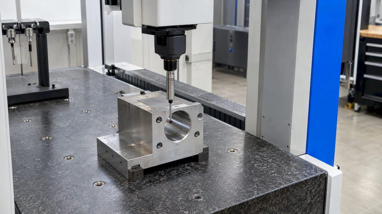
Parallelism inspection answers one question: does a surface, axis or line stay within the stated tolerance zone relative to its datum? On the shop floor, you seat the datum feature on a reference surface, sweep the controlled feature with an indicator or probe, and take the spread between the highest and lowest readings. If that spread is larger than the tolerance on the drawing, the part fails. The method is simple. The errors come from datum setup, a weak measuring system and a result that never gets tied back to the right drawing dimension. This guide covers all three, so your team's numbers hold up in an audit.
TL;DR
- Parallelism is an orientation control. It needs a datum, and it limits how far a feature may tilt relative to that datum.
- For a surface, the tolerance zone is two parallel planes, set apart by the stated tolerance, that are themselves parallel to the datum.
- On a surface plate, parallelism error is the highest indicator reading minus the lowest across the controlled surface. Compare it with the drawing tolerance.
- A CMM gives denser data, but it needs a correctly established datum, or the report only looks precise.
- Link every measured value to its ballooned drawing characteristic, so the pass or fail result is traceable.
Table of Contents
- What parallelism controls
- Parallelism versus flatness
- Tolerance zones: surfaces and axes
- How to measure parallelism on a surface plate
- Calculating parallelism and deciding pass or fail
- Inspecting parallelism on a CMM
- Where parallelism inspections go wrong
- From reading to audit-ready report
- Our perspective
- FAQ
- Sources
What parallelism controls
Parallelism is an orientation tolerance. It compares a controlled feature with a datum, a reference plane or line, and the datum is required. KEYENCE's overview of orientation tolerances states it this way: a parallelism callout specifies that two lines or planes are parallel, with a datum doing the referencing.
In the feature control frame, you read the callout left to right:
- The parallelism symbol (two slanted parallel lines).
- The tolerance value, with a diameter symbol if the zone is cylindrical.
- The datum reference, usually a single letter such as A.
The frame can be attached to the controlled surface or to its extension line. The referenced datum feature then establishes the datum, as Engineering Essentials explains.
Parallelism also constrains the form of the feature within its zone, but it controls no location. Dimensional Consulting notes this limit directly. A surface can sit anywhere in space and still be parallel, so the part's size and location dimensions have to carry the rest of the requirement.
If you want to see how datums behave when a fixture does not match the drawing, read our notes on why GD&T datums go wrong at the fixture before you set up the measurement.
Parallelism versus flatness
Inspectors mix these two up more than any other pair of controls. Flatness evaluates a surface against itself and needs no datum. Parallelism evaluates a surface against a datum, so it also catches tilt. Tooling & Production makes the point that a face can be perfectly flat and still tilted relative to the datum, so the two are never interchangeable.
Here is a practical way to keep them apart:
| Question | Flatness | Parallelism |
|---|---|---|
| Datum required? | No | Yes |
| What is compared? | The surface with itself | The surface with the datum |
| Catches tilt? | No | Yes |
| Limits form? | Yes | Yes, within its zone |
When a drawing calls out both, inspect them as two separate characteristics. The parallelism tolerance is normally larger than the flatness tolerance, because it has to leave room for the form error. For flatness setups and evaluation, see our guide to flatness inspection.
Tolerance zones: surfaces and axes
The zone depends on what the callout controls.
Surface parallelism
For a surface, the zone is two parallel planes, separated by the tolerance value, that are parallel to the datum plane. Engineers Edge describes the same zone for a surface, a median plane, an axis or a line. Every point on the controlled surface must lie between those two planes. The planes can float in height above the datum, as long as they stay parallel to it and the part's size limits are respected.
Axis parallelism
For an axis, such as a bored hole parallel to a base, the frame can include a diameter symbol. The zone then becomes a cylinder, and the axis has to stay inside it, parallel to the datum. eMachineShop's definition describes this cylindrical zone. When the frame has no diameter symbol, the zone is a pair of parallel planes instead, so the direction you measure in matters. For more on parallelism applied to an axis and how the tolerance zone is built, see that explanation of precision testing on CNC-made features.
If the callout reaches into a mating part, such as a pin that protrudes from a hole, a projected tolerance zone may apply. We cover that case in projected tolerance zones in GD&T.
Which standard applies
In the United States, GD&T callouts follow the ASME Y14.5 standard. The edition the drawing cites decides the rules, so read the drawing's general notes first. Engineers Edge lists revisions from 1982, 1994, 2009 and 2018, and ASME's own GD&T handbook listing shows that the 2009 edition is still taught from. Confirm the edition on ASME's site before you write it into a procedure. Teams that work to ISO drawings, common in the UK, France and Germany, should check the ISO parallelism rules named in the title block instead.
How to measure parallelism on a surface plate
The surface plate method is the standard manual check. It needs a granite plate, a stand or fixture, and a dial or electronic indicator. A height gage with a dial indicator on a plate works for the same check, and the Marvin Group inspection handbook lists that setup as suitable for parallelism. The steps below follow the common shop-floor routine described by Xometry Pro: datum face on a clean plate, indicator traversed across the inspected face.
- Read the drawing. Identify the controlled feature, the tolerance value, the datum letter and whether the frame carries a diameter symbol. In QA-Report, the ballooned drawing gives each characteristic its own number, so the callout and the result stay together from the start.
- Clean everything. Wipe the plate, the datum face and the indicator contact point. A chip under the part tilts it, and the tilt shows up as false parallelism error.
- Seat the datum feature on the plate. The plate simulates the datum, as Engineering Essentials describes. Make sure the part rests on the high points of the datum feature and is stable, not rocking. Clamp it lightly if needed, without distorting it.
- Zero the indicator at a start point. Set the indicator at a fixed height on the controlled surface. Use a stand that does not flex, and keep the contact point square to the surface.
- Sweep the surface. Move the part, or the indicator, across the whole controlled surface in a grid or raster. One shop-floor guide recommends sweeping the top with the indicator at constant height. The more of the surface you cover, the less likely you are to miss a high or low area.
- Record the highest and lowest readings. Note both values with their signs. Do not rely on the final reading alone.
- Calculate and decide. The next section shows how.
- Record the result against the characteristic. Enter the reading with the instrument ID and the date. Where it goes wrong: a result on a scrap of paper that does not name the balloon number cannot be traced.
A step-by-step example of the surface plate inspection method in a workshop setting shows the same traverse with the datum face seated on the plate.
For the same reason, never improvise the datum. If the part cannot sit stably on its datum feature, the fixture or the drawing needs attention first. Our guide to GD&T datums for inspection teams explains how datum choices cause false rejects.
Calculating parallelism and deciding pass or fail
The rule is direct. The surface fails if the indicator's full movement exceeds the parallelism tolerance, as Engineering Essentials states. Full indicator movement is simply the difference between the highest and lowest readings over the whole sweep.

Xometry Pro's published example subtracts the lowest reading from the highest: 0.08 mm minus 0.02 mm gives 0.06 mm of parallelism error.
Here is a worked example in inches, with made-up numbers for illustration:
- Drawing callout: parallelism 0.002 in. to datum A.
- Highest indicator reading: +0.0013 in.
- Lowest indicator reading: -0.0004 in.
- Parallelism error: 0.0013 - (-0.0004) = 0.0017 in.
- Result: 0.0017 in. is less than 0.002 in., so the feature passes.
Note the double negative. Subtracting a negative reading adds to the spread, and that is the step people get wrong most often. If the lowest reading had been -0.0008 in., the error would be 0.0021 in. and the part would fail.
Two cautions about the number itself:
- The measuring equipment has to suit the tolerance. A metrology forum thread makes the same basic point: establish the datum plane, compare the other surface to it, and use equipment that fits the tolerance.
- Reading uncertainty eats into your margin. A part measuring close to the limit deserves a second look with a better setup. For the concept of repeatability and reproducibility in gages, which tells you how much of a reading is the instrument, see gage repeatability and reproducibility.
Inspecting parallelism on a CMM
A coordinate measuring machine (CMM) is the alternative when the tolerance is tight, the feature is an axis or the part cannot sit flat on a plate. Xometry Pro notes that the surface plate method is a practical fallback when a CMM is unavailable, and that the CMM probes the reference surface to establish the datum before probing the controlled surface. The software then finds the minimum separation of two parallel planes containing the sampled points. That separation is the parallelism error.
CMM programs can generate reports after initial setup, but the same Marvin Group handbook cautions that CMM algorithms interpolate touch points to build features such as datum planes. That can give an impression of precision that exceeds the real measurement accuracy. Modern Machine Shop's George Schuetz adds that plate grade adds error, and a probe samples only selected points, so it cannot inspect every point on a surface.
Practical consequences:
- Use enough points to cover the surface, spread across it, not clustered near an edge.
- Build the datum from the datum feature as the drawing defines it, not from a convenient surface.
- Check that the program's datum order matches the frame.
Our CMM data import guide shows how results flow into inspection reports, and the CMM inspection software page lists what the platform handles. QA-Report imports CMM data and maps it to ballooned drawing characteristics, which takes the retyping out of the step where most transcription errors occur.
Where parallelism inspections go wrong
Most bad parallelism results come from setup, not arithmetic. These are the patterns to watch for:
- Wrong datum. The part is seated on a surface the drawing never named. The number looks plausible and is meaningless.
- Rocking part. A datum face that is not flat touches at three high points. Re-seat it, then verify the part is stable before reading.
- Mixed up controls. Flatness measured and reported as parallelism, or the reverse.
- Sign mistakes. Subtracting readings without their signs, as in the example above.
- Partial coverage. Sweeping one line of the surface and calling it done.
- Unclear method. Customer and supplier use different setups for the same callout. One practitioner thread suggests the cleanest fix: ask your customer how they inspect it so both sides speak the same language. Record the method in the report either way.
- Result not linked to the drawing. The measured value exists, but nobody can show which dimension it belongs to. Broken traceability is like a broken chain: it fails at its weakest link, and in an audit that link is usually the paperwork.
When the callout is a surface profile instead, the evaluation changes. See our guides on surface profile tolerance and profile tolerance inspection for that case, and on concentricity for axis relationships that are often confused with parallelism.
From reading to audit-ready report
Measuring is half the job. A first article inspection or PPAP package needs every result tied to a ballooned characteristic, with the nominal, tolerance, actual and pass or fail status in one place. QA-Report is built for that workflow: automatic drawing ballooning with AI auto-numbering, a measurement wizard that links ballooned dimensions to measured results, out-of-tolerance detection, GD&T support and PDF reports for AS9102 and PPAP submissions.
The Free plan costs $0 per month. Basic is $49.99 per month and PRO is $149.99 per month. On-Premise and Enterprise Solutions are available for larger or data-sensitive operations, and their pricing is not published. You can compare the plans on the QA-Report pricing page.

If your team still keeps parallelism readings in notebooks or spreadsheets, start with one part number. Balloon the drawing, enter the readings against the characteristic and let the platform flag anything out of tolerance. You can try it from the QA-Report home page.
Our perspective
Parallelism rarely fails because someone cannot subtract two numbers. It fails because the datum was not what the drawing said it was, or because the result was recorded somewhere nobody can connect to the characteristic.
We build QA-Report around that second problem. A ballooned drawing gives each dimension an identity, and the measured value attaches to that identity, whether it came from an indicator on a plate or from a CMM file. Out-of-tolerance values are flagged as soon as they are entered, so an inspector sees a failing characteristic while the part is still on the plate.
We also think inspection and production should not live in separate tools. Parts, batches, routes and rejections in one platform keep the story of a part complete: what was made, how it was checked and what happened when it was not right.
For regulated work in aerospace, automotive and medical devices, the report is the product the customer sees. We want it to be as disciplined as the measurement behind it.
Michael Chen
FAQ
How do you check parallelism?
Seat the datum feature on a surface plate, then sweep an indicator across the controlled surface at constant height. Subtract the lowest reading from the highest. If the result is larger than the tolerance on the drawing, the feature is out of tolerance. For tight tolerances or axes, use a CMM.
What is the difference between parallelism and flatness?
Flatness controls a surface against itself and has no datum. Parallelism controls the surface against a datum, so it also limits tilt. A surface can be flat and still fail parallelism if it is tilted relative to the datum, as Tooling & Production explains.
Does parallelism control location?
No. Parallelism controls orientation and, within its zone, form, but it controls no location. Size and location dimensions on the drawing still have to be inspected separately.
What tolerance zone does an axis get?
When the feature control frame has a diameter symbol, the axis must lie within a cylindrical zone parallel to the datum, as eMachineShop describes. Without the symbol, the zone is a pair of parallel planes.
Can I measure parallelism without a CMM?
Yes. A surface plate with a dial indicator or a height gage works for many parts, and the Marvin Group handbook lists that equipment as suitable. Match the instrument's resolution to the tolerance, then record the result against the drawing characteristic.
Sources
- KEYENCE: Orientation Tolerance
- eMachineShop: GD&T Parallelism Definition
- Dimensional Consulting: Parallelism
- Engineering Essentials: Parallelism of a Surface
- Engineers Edge: GD&T Parallelism Tolerance Review and Simulator
- Tooling & Production: Flatness and parallelism are never synonymous
- ASME: Geometric Dimensioning and Tolerancing Handbook
- Xometry Pro: Parallelism GD&T
- SpinStop: Easy Guide to GD&T Parallelism
- Marvin Group: Inspection Handbook for Sheet Metal
- Modern Machine Shop: Measuring for Flatness, Thickness and Parallelism
- Elsmar Cove: Calculating (Approximate) Parallelism
- JM-TRONIK: DCNC testing and precision
- MSI Certified: Define Gage Repeatability and Reproducibility
- MIY Makerspace: surface plate method